 SURFACE
VEHICLE
STANDARD
SAE Technical Standards Board Rules provide that: “This report is published by SAE to advance the state of technical and engineering
sciences. The use of this report is entirely voluntary, and its applicability and suitability for any particular use, including any patent
infringement arising therefrom, is the sole responsibility of the user.”
SAE reviews each technical report at least every five years at which time it may be reaffirmed, revised, or cancelled. SAE invites your
written comments and suggestions.
Copyright 2008 Society of Automotive Engineers, Inc.
All rights reserved.
Printed in U.S.A.
Issued
TBD
Revised
Superseding
None
DRAFT SAE J2735 D
EDICATED
S
HORT
R
ANGE
COMMUNICATIONS (DSRC) MESSAGE S
ET
DICTIONARY
Forward
This 2nd edition of the standard provides additional DSRC messages developed beyond
those defined in the first edition and incorporating feedback from early deployment
experience. A uniform method of message encoding, using ASN.1 DER encoding,
replaces the implicit binary encoding developed in the first edition, although some binary
encoding remains in selected messages for efficiency. The messages defined in this
edition have been designed to support deployment in such a way as to remain compatible
with additional further planned message content, still in development at this time.
Prepared for use by the DSRC committee of the SAE by SubCarrier Systems Corp ( SCSC ).
Copyright 2008, Society of Automotive Engineers ( www.SAE.org )
Create_time:
02:54:46 PM Thursday, December 11, 2008
Extracted from:
Dsrc_rev029.ITS
[Mod: 12/11/2008 2:49:16 PM]
Table of Contents
1. Scope..............................................................................................................................10
1.1
Purpose..................................................................................................................10
2. References
....................................................................................................................10
3. Terms and definitions
...................................................................................................12
3.1 Definitions
..................................................................................................................12
3.2 Abbreviations and acronyms......................................................................................21
4
The use of DSRC messages in Applications..............................................................23
4.1
Introduction to DSRC Goals and Objectives
.........................................................23
4.2
DSRC Overview
....................................................................................................24
4.3
Philosophy of Message Design
...............................................................................24
|
 SAE J2735-Draft-Rev29 [issued: 12-11-08]
-
2
-
This is an SAE Motor Vehicle Council draft document of the DSRC committee, subject to change.
5. Message Sets..................................................................................................................25
5.1 Message: MSG_Ala Carte..........................................................................................26
5.2 Message: MSG_BasicSafetyMessage_Verbose
...........................................................26
5.3 Message: MSG_BasicSafetyMessage
..........................................................................27
5.4 Message: MSG_EmergencyVehicleAlert....................................................................29
5.5 Message: MSG_IntersectionCollisionAvoidance
........................................................30
5.6 Message: MSG_NMEA_Corrections..........................................................................31
5.7 Message: MSG_ProbeVehicleData.............................................................................32
5.8 Message: MSG_RoadSideAlert
..................................................................................33
5.9 Message: MSG_RTCM_Corrections..........................................................................35
5.10 Message: MSG_TravelerInformation.......................................................................36
6. Data Frames
..................................................................................................................39
6.1 Data Element: DF_AccelerationSet4Way...................................................................39
6.2 Data Frame: DF_AccelSteerYawRateConfidence
......................................................40
6.3 Data Frame: DF_Approach
.......................................................................................40
6.4 Data Frame: DF_ApproachesObject
..........................................................................41
6.5 Data Frame: DF_BarrierLane
...................................................................................42
6.6 Data Frame: DF_BreadCrumbVersion-1...................................................................43
6.7 Data Element: DF_BSM_Blob
...................................................................................45
6.8 Data Frame: DF_BumperHeights
..............................................................................46
6.9 Data Frame: DF_Circle..............................................................................................46
6.10 Data Frame: DF_ConfidenceSet...............................................................................47
6.11 Data Element: DF_ConnectsTo................................................................................48
6.12 Data Frame: DF_CrosswalkLane.............................................................................49
6.13 Data Frame: DF_DataParameters............................................................................49
6.14 Data Frame: DF_DDate
...........................................................................................50
6.15 Data Frame: DF_DDateTime
...................................................................................51
6.16 Data Frame: DF_DFullTime
....................................................................................51
6.17 Data Frame: DF_DMonthDay..................................................................................52
6.18 Data Frame: DF_DTime...........................................................................................52
6.19 Data Frame: DF_DYearMonth
................................................................................53
6.20 Data Frame: DF_FullPositionVector........................................................................53
6.21 Data Frame: DF_Intersection...................................................................................54
6.22 Data Frame: DF_ITIS_Phrase_ExitService..............................................................56
6.23 Data Frame: DF_ITIS_Phrase_GenericSignage.......................................................56
6.24 Data Frame: DF_ITIS_Phrase_SpeedLimit
.............................................................57
6.25 Data Frame: DF_ITIS_Phrase_WorkZone
..............................................................57
6.26 Data Frame: DF_J1939-Data Items..........................................................................58
6.27 Data Frame: DF_MovementState.............................................................................59
6.28 Data Frame: DF_NodeList
.......................................................................................61
6.29 Data Frame: DF_Offsets
..........................................................................................62
6.30 Data Frame: DF_Position2D
....................................................................................63
6.31 Data Frame: DF_Position3D
....................................................................................64
6.32 Data Element: DF_PositionConfidenceSet
...............................................................64
6.33 Data Frame: DF_ReferencePoint
.............................................................................65
6.34 Data Frame: DF_RoadSignID..................................................................................66
6.35 Data Frame: DF_Sample..........................................................................................66
6.36 Data Frame: DF_ShapePointSet...............................................................................67
6.37 Data Frame: DF_SignalControlZone
.......................................................................67
|
 SAE J2735-Draft-Rev29 [issued: 12-11-08]
-
3
-
This is an SAE Motor Vehicle Council draft document of the DSRC committee, subject to change.
6.38 Data Frame: DF_SignalRequest...............................................................................69
6.39 Data Frame: DF_SnapshotDistance
.........................................................................70
6.40 Data Frame: DF_Snapshot.......................................................................................71
6.41 Data Frame: DF_SnapshotTime...............................................................................71
6.42 Data Frame: DF_SpecialLane
..................................................................................72
6.43 Data Element: DF_SpeedandHeadingConfidence
....................................................73
6.44 Data Frame: DF_UpdateVector
...............................................................................74
6.45 Data Frame: DF_ValidRegion..................................................................................74
6.46 Data Frame: DF_VehicleComputedLane
.................................................................75
6.47 Data Frame: DF_VehicleIdent
.................................................................................76
6.48 Data Frame: DF_VehicleMotionTrail
......................................................................77
6.49 Data Frame: DF_VehicleReferenceLane
..................................................................80
6.50 Data Frame: DF_VehicleSize
...................................................................................81
6.51 Data Frame: DF_VehicleStatusRequest
...................................................................82
6.52 Data Frame: DF_VehicleStatus................................................................................82
6.53 Data Frame: DF_WiperStatus..................................................................................86
7. Data Elements
...............................................................................................................88
7.1 Data Element: DE_Acceleration.................................................................................88
7.2 Data Element: DE_AccelerationConfidence...............................................................88
7.3 Data Element: DE_AmbientAirPressure (Barometric Pressure)................................90
7.4 Data Element: DE_AmbientAirTemperature.............................................................90
7.5 Data Element: DE_AntiLockBrakeStatus
..................................................................91
7.6 Data Element: DE_ApproachNumber........................................................................91
7.7 Data Element: DE_BarrierAttributes
........................................................................92
7.8 Data Element: DE_BrakeAppliedPressure.................................................................93
7.9 Data Element: DE_BrakeAppliedStatus.....................................................................94
7.10 Data Element: DE_BrakeBoostApplied....................................................................95
7.11 Data Element: DE_BrakeSystemStatus....................................................................96
7.12 Data Element: DE_BreadCrumbVersion-10
............................................................97
7.13 Data Element: DE_BreadCrumbVersion-2..............................................................98
7.14 Data Element: DE_BreadCrumbVersion-3..............................................................99
7.15 Data Element: DE_BreadCrumbVersion-4............................................................100
7.16 Data Element: DE_BreadCrumbVersion-5............................................................100
7.17 Data Element: DE_BreadCrumbVersion-6............................................................101
7.18 Data Element: DE_BreadCrumbVersion-7............................................................102
7.19 Data Element: DE_BreadCrumbVersion-8............................................................103
7.20 Data Element: DE_BreadCrumbVersion-9............................................................104
7.21 Data Element: DE_BumperHeightFront
................................................................104
7.22 Data Element: DE_BumperHeightRear
.................................................................105
7.23 Data Element: DE_CodeWord
...............................................................................105
7.24 Data Element: DE_CoefficientOfFriction...............................................................106
7.25 Data Element: DE_Collision Event Flag (remove now, use event flags)
.................106
7.26 Data Element: DE_ColorState................................................................................107
7.27 Data Element: DE_CrosswalkLaneAttributes........................................................108
7.28 Data Element: DE_DDay........................................................................................109
7.29 Data Element: DE_DescriptiveName......................................................................109
7.30 Data Element: DE_DHour
.....................................................................................110
7.31 Data Element: DE_DMinute
..................................................................................110
7.32 Data Element: DE_DMonth
...................................................................................111
|
 SAE J2735-Draft-Rev29 [issued: 12-11-08]
-
4
-
This is an SAE Motor Vehicle Council draft document of the DSRC committee, subject to change.
7.33 Data Element: DE_DOffset
....................................................................................112
7.34 Data Element: DE_DrivenLineOffset.....................................................................112
7.35 Data Element: DE_DrivingWheelAngle
.................................................................112
7.36 Data Element: DE_DSecond...................................................................................113
7.37 Data Element: DE_DSignalSeconds
.......................................................................113
7.38 Data Element: DE_DSRC MessageID
....................................................................114
7.39 Data Element: DE_DYear
......................................................................................116
7.40 Data Element: DE_ElectronicStablityControlStatus REMOVE (dupe)..................116
7.41 Data Element: DE_ElevationConfidence................................................................117
7.42 Data Element: DE_Elevation..................................................................................118
7.43 Data Element: DE_EmergencyDetails....................................................................119
7.44 Data Element: DE_EventFlags
...............................................................................120
7.45 Data Element: DE_Extent
......................................................................................122
7.46 Data Element: DE_ExteriorLights
.........................................................................123
7.47 Data Element: DE_FurtherInfoID
.........................................................................124
7.48 Data Element: DE_GPSstatus
................................................................................125
7.49 Data Element: DE_HeadingConfidence
.................................................................126
7.50 Data Element: DE_Heading
...................................................................................127
7.51 Data Element: DE_HeadingSlice............................................................................128
7.52 Data Element: DE_Intersection Status Object........................................................129
7.53 Data Element: DE_IntersectionID..........................................................................130
7.54 Data Element: DE_J1939-71-Axle Location
...........................................................131
7.55 Data Element: DE_J1939-71-Axle Weight..............................................................131
7.56 Data Element: DE_J1939-71-Cargo Weight
...........................................................131
7.57 Data Element: DE_J1939-71-Drive Axle Lift Air Pressure.....................................131
7.58 Data Element: DE_J1939-71-Drive Axle Location..................................................132
7.59 Data Element: DE_J1939-71-Drive Axle Lube Pressure.........................................132
7.60 Data Element: DE_J1939-71-Drive Axle Temperature...........................................132
7.61 Data Element: DE_J1939-71-Steering Axle Lube Pressure
....................................133
7.62 Data Element: DE_J1939-71-Steering Axle Temperature
......................................133
7.63 Data Element: DE_J1939-71-Tire Leakage Rate
....................................................133
7.64 Data Element: DE_J1939-71-Tire Location............................................................133
7.65 Data Element: DE_J1939-71-Tire Pressure Threshold Detection
...........................134
7.66 Data Element: DE_J1939-71-Tire Pressure............................................................135
7.67 Data Element: DE_J1939-71-Tire Temp
................................................................135
7.68 Data Element: DE_J1939-71-Trailer Weight..........................................................135
7.69 Data Element: DE_J1939-71-Wheel End Elect. Fault.............................................135
7.70 Data Element: DE_J1939-71-Wheel Sensor Status
.................................................136
7.71 Data Element: DE_LaneManeuverCode
................................................................137
7.72 Data Element: DE_LaneNumber
...........................................................................138
7.73 Data Element: DE_LaneSet....................................................................................139
7.74 Data Element: DE_LaneWidth...............................................................................139
7.75 Data Element: DE_Latitude
...................................................................................140
7.76 Data Element: DE_LayerID
...................................................................................141
7.77 Data Element: DE_LayerType
...............................................................................141
7.78 Data Element: DE_LightbarInUse
.........................................................................142
7.79 Data Element: DE_Longitude
................................................................................143
7.80 Data Element: DE_MAYDAY_Location_quality_code
..........................................144
7.81 Data Element: DE_MAYDAY_Location_tech_code
...............................................145
|
 SAE J2735-Draft-Rev29 [issued: 12-11-08]
-
5
-
This is an SAE Motor Vehicle Council draft document of the DSRC committee, subject to change.
7.82 Data Element: DE_MinuteOfTheYear
...................................................................145
7.83 Data Element: DE_MinutesDuration
.....................................................................146
7.84 Data Element: DE_MsgCount................................................................................146
7.85 Data Element: DE_MsgCRC..................................................................................147
7.86 Data Element: DE_MultiVehicleReponse...............................................................148
7.87 Data Element: DE_MUTCDCode
..........................................................................148
7.88 Data Element: DE_NEMA_Revision......................................................................149
7.89 Data Element: DE_NMEA_MsgType
.....................................................................150
7.90 Data Element: DE_NMEA_Payload.......................................................................150
7.91 Data Element: DE_NTCIPVehicleclass,
.................................................................150
7.92 Data Element: DE_ObstacleDirection
....................................................................151
7.93 Data Element: DE_ObstacleDistance
.....................................................................152
7.94 Data Element: DE_PayloadData
............................................................................152
7.95 Data Element: DE_Payload
....................................................................................153
7.96 Data Element: DE_PedestrianDetect......................................................................153
7.97 Data Element: DE_PedestrianSignalState
..............................................................154
7.98 Data Element: DE_PositionalAccuracy
..................................................................155
7.99 Data Element: DE_PositionConfidence
..................................................................156
7.100 Data Element: DE_PreemptState
.........................................................................157
7.101 Data Element: DE_Priority
..................................................................................158
7.102 Data Element: DE_PriorityState
..........................................................................159
7.103 Data Element: DE_ProbeSegmentNumber...........................................................160
7.104 Data Element: DE_RainSensor
............................................................................161
7.105 Data Element: DE_RequestedItem
.......................................................................162
7.106 Data Element: DE_ResponseType
........................................................................165
7.107 Data Element: DE_RTCM_ID..............................................................................166
7.108 Data Element: DE_RTCM_Payload (REMOVE)
.................................................166
7.109 Data Element: DE_RTCM_Revision (REMOVE)
................................................167
7.110 Data Element: DE_SignalLightState
....................................................................168
7.111 Data Element: DE_SignalReqScheme...................................................................169
7.112 Data Element: DE_SignalState
.............................................................................170
7.113 Data Element: DE_SignPrority
............................................................................172
7.114 Data Element: DE_SirenInUse
.............................................................................172
7.115 Data Element: DE_SpecialLaneAttributes
...........................................................173
7.116 Data Element: DE_SpecialSignalState..................................................................174
7.117 Data Element: DE_SpeedConfidence....................................................................174
7.118 Data Element: DE_Speed
.....................................................................................175
7.119 Data Element: DE_StabilityControlStatus (DUPE)
.............................................176
7.120 Data Element: DE_StateConfidence
.....................................................................177
7.121 Data Element: DE_StdTagList OUTDATED
......................................................178
7.122 Data Element: DE_SteeringWheelAngleConfidence.............................................182
7.123 Data Element: DE_SteeringWheelAngleRateOfChange
.......................................183
7.124 Data Element: DE_SteeringWheelAngle
..............................................................183
7.125 Data Element: DE_SunSensor..............................................................................184
7.126 Data Element: DE_TemporaryID.........................................................................185
7.127 Data Element: DE_TerminationDistance
.............................................................185
7.128 Data Element: DE_TerminationTime...................................................................186
7.129 Data Element: DE_ThrottleConfidence
................................................................186
7.130 Data Element: DE_ThrottlePosition
.....................................................................187
|
 SAE J2735-Draft-Rev29 [issued: 12-11-08]
-
6
-
This is an SAE Motor Vehicle Council draft document of the DSRC committee, subject to change.
7.131 Data Element: DE_TimeConfidence
.....................................................................187
7.132 Data Element: DE_TimeToChange,
.....................................................................190
7.133 Data Element: DE_TractionControlState.............................................................191
7.134 Data Element: DE_TransistStatus........................................................................191
7.135 Data Element: DE_TransitPreEmptionRequest
...................................................192
7.136 Data Element: DE_TransmitInterval
...................................................................193
7.137 Data Element: DE_TravelerInfoType...................................................................193
7.138 Data Element: DE_UniqueMSG_ID
.....................................................................194
7.139 Data Element: DE_URL_Base..............................................................................195
7.140 Data Element: DE_URL_Link..............................................................................195
7.141 Data Element: DE_URL_Short
............................................................................196
7.142 Data Element: DE_VehicleHeight
........................................................................196
7.143 Data Element: DE_VehicleLaneAttributes
...........................................................196
7.144 Data Element: DE_VehicleLength
........................................................................198
7.145 Data Element: DE_VehicleMass...........................................................................198
7.146 Data Element: DE_VehicleRequestStatus.............................................................199
7.147 Data Element: DE_VehicleStatusDeviceTypeTag
.................................................200
7.148 Data Element: DE_VehicleType
...........................................................................202
7.149 Data Element: DE_VehicleWidth
.........................................................................203
7.150 Data Element: DE_VerticalAccelerationThreshold
..............................................204
7.151 Data Element: DE_VerticalAcceleration
..............................................................205
7.152 Data Element: DE_VINstring,..............................................................................205
7.153 Data Element: DE_WiperRate
.............................................................................206
7.154 Data Element: DE_WiperStatusFront..................................................................206
7.155 Data Element: DE_WiperStatusRear
...................................................................207
7.156 Data Element: DE_YawRateConfidence
..............................................................208
7.157 Data Element: DE_YawRate
................................................................................210
8. External Data Entries
.................................................................................................211
8.1 Data Element: DE_Incident Response Equipment [ITIS].........................................211
8.2 Data Element: DE_ITIS_Text [ITIS]
.......................................................................214
8.3 Data Element: DE_Responder Group Affected [ITIS]
.............................................214
8.4 Data Element: DE_Vehicle Groups Affected [ITIS]
.................................................215
8.5 Data Frame: DF_ITIS-Codes_And_Text [ITIS].......................................................217
8.6 Data Element: ESS_EssMobileFriction [NTCIP]
.....................................................218
8.7 Data Element: ESS_EssPrecipRate_quantity [NTCIP]
............................................218
8.8 Data Element: ESS_EssPrecipSituation_code [NTCIP]
...........................................218
8.9 Data Element: ESS_EssPrecipYesNo_code [NTCIP]
...............................................220
8.10 Data Element: ESS_EssSolarRadiation_quantity [NTCIP]
....................................220
8.11 Data Element: EXT_ITIS_Codes [ITIS].................................................................220
9. Coming Attractions, Data Concepts
...........................................................................222
9.1 Message: MSG_CommonSafetyRequest
..................................................................222
9.2 Message: MSG_MapData (GID Layer)....................................................................223
9.3 Message: MSG_ProbeDataManagement..................................................................224
9.4 Message: MSG_SignalPhaseAndTimingMessage (SPAT)
........................................225
9.5 Message: MSG_SignalRequestMessage....................................................................226
9.6 Message: MSG_SignalStatusMessage
......................................................................227
10. Conformance............................................................................................................229
|
 SAE J2735-Draft-Rev29 [issued: 12-11-08]
-
7
-
This is an SAE Motor Vehicle Council draft document of the DSRC committee, subject to change.
11.
Other Application Notes (Informative)
................................................................229
11.1
On the use of TIME.............................................................................................229
11.2
Persistence of the temporary MAC ID field
.........................................................229
11.3
URLs used in the standard
..................................................................................230
Annex A Message Framework
.....................................................................................230
Introduction
..................................................................................................................230
Priority Related Terms..................................................................................................231
Message Priority Enforcement
......................................................................................232
Message Priority Table..................................................................................................232
Adjusting Priority..........................................................................................................233
Latency Ranges
.............................................................................................................233
General Message Priority Scheme
.................................................................................233
Message Priority Table..................................................................................................233
Annex B The Safety Message Handler (Informative)
.................................................236
Annex C Operation with the Vehicle Basic Safety Message
.......................................238
1.
Application Background......................................................................................238
2.
Applicable documents..........................................................................................239
3.
Application message sequences
............................................................................239
4.
Application use with DSRC
.................................................................................239
Annex C-1 Intersection Collision Warning
..................................................................240
Application Description
.................................................................................................240
Concept of Operations
...................................................................................................240
Sensors and Other System Needs...................................................................................241
Annex C-2 Emergency Electronic Brake Lights
..........................................................241
Application Description
.................................................................................................241
Flow of Events
...............................................................................................................241
Concept of Operation
....................................................................................................242
Sensors and Other System Needs...................................................................................242
Annex C-3 Pre-crash Sensing
.......................................................................................242
Application Description.................................................................................................242
Concept of Operations
...................................................................................................243
Sensors and Other System Needs...................................................................................243
Annex C-4 Cooperative Forward Collision Warning..................................................243
Application Description
.................................................................................................243
Concept of Operations
...................................................................................................244
Sensors and Other System Needs...................................................................................244
Annex C-5 Left Turn Assistant......................................................................................244
Application Description
.................................................................................................244
Concept of Operations
...................................................................................................245
Sensors and Other System Needs...................................................................................245
Annex C-6 Stop Sign Movement Assistance
..................................................................245
Application Description
.................................................................................................245
Concept of Operations
...................................................................................................246
Sensors and Other System Needs...................................................................................246
|
 SAE J2735-Draft-Rev29 [issued: 12-11-08]
-
8
-
This is an SAE Motor Vehicle Council draft document of the DSRC committee, subject to change.
Annex C-7 Lane Change Warning...............................................................................246
Application Description
.................................................................................................246
Concept of Operations
...................................................................................................247
Sensors and Other System Needs...................................................................................247
Annex D: Traveler Information Message Use and Operation......................................248
Traveler Information Introduction................................................................................248
Traveler Information Packet Structure
.........................................................................248
Packet Format Diagram
................................................................................................250
Traveler Advisory Example
...........................................................................................250
Road Sign Example
.......................................................................................................252
Application and Use with DSRC
....................................................................................252
Handling Repeated Packets
...........................................................................................................................253
Handling Newly Received Data Frames.....................................................................................................254
Replacement Policy for Locally-Stored Messages
...................................................................................255
Pruning Messages by In-vehicle Housekeeping........................................................................................
255
Updated Messages from Network
...............................................................................................................
256
Deleting Messages as Directed by Network User.....................................................................................
256
Vehicle Power-Up Events.............................................................................................................................
256
Presentation of Signs & Advisories in Vehicle
...............................................................256
Valid Time
.........................................................................................................................................................256
Valid
Region
.....................................................................................................................................................258
Circular Region.................................................................................................................................................258
Polygon Region..................................................................................................................................................259
Shape Point Set Region
...................................................................................................................................260
Extremely Large Regions
...............................................................................................................................261
Annex E Traffic Probe Message Use and Operation
....................................................262
Probe Data Introduction................................................................................................262
Probe Message Structure...............................................................................................262
Application and Use with DSRC
....................................................................................264
Probe Snapshot Generation
...........................................................................................264
Periodic Snapshots.........................................................................................................265
Event Triggered Snapshots
............................................................................................267
Starts and Stops Snapshots
............................................................................................267
Message Transmission Order
........................................................................................267
Probe Data Message Sets Received By an RSU
..............................................................271
Vehicle Anonymity
........................................................................................................271
Probe Data Security.......................................................................................................271
Probe Data Message Management.................................................................................271
Probe Message Management: Time or Distance Periodic Snapshot Generation
...........272
Probe Message Management: Interval between Probe Message Broadcasts
.................273
Probe Message Management: Termination...................................................................273
Probe Message Management: Vehicle Status Element Triggers....................................273
Probe Message Management: Vehicle Sampling
...........................................................273
Probe Message Management: Managed Vehicle Heading.............................................274
Probe Message Management: Start and Stop Threshold Settings
.................................274
|
 SAE J2735-Draft-Rev29 [issued: 12-11-08]
-
9
-
This is an SAE Motor Vehicle Council draft document of the DSRC committee, subject to change.
Annex F Emergency Vehicle Message Use and Operation.........................................276
1. Application Description
............................................................................................276
2. Preconditions for operation:
.....................................................................................277
3. Flow of Events...........................................................................................................277
4. System Architecture and Concept of Operation........................................................279
5. Application use with DSRC.......................................................................................280
Annex G Roadside Alerting Message Use and Operation...........................................282
1. Application Description
............................................................................................282
2. Preconditions for operation:
.....................................................................................282
3. Flow of Events...........................................................................................................282
4. System Architecture and Concept of Operation........................................................283
5. Application use with DSRC.......................................................................................283
Annex H Map and SPAT Message Use and Operation...............................................285
1.
Introduction
........................................................................................................285
2.
The overall framework of the SPAT
....................................................................285
3.
The overall framework of the MAP
.....................................................................288
4. Additional details of message use
..............................................................................291
Annex I Cooperative Cruse Control (CCC) Use and Operation
.................................292
1. Introduction..............................................................................................................292
2. Operational Concept
....................................................................................................292
3. Cooperative Cruise Control Message Set
..................................................................293
4. Form and Join Message Operations
..........................................................................293
Join Message Request/Response...................................................................................................................295
Form Message Request
...................................................................................................................................296
5. RSE Broadcast Operations
.......................................................................................296
Roadside Broadcast Message.........................................................................................................................298
6. Leave Team Message Operations..............................................................................298
Leave Message Broadcast...............................................................................................................................299
6. Team Status Message Operations..............................................................................299
7. Conclusion
................................................................................................................300
8. Developer Notes
........................................................................................................301
Vehicle Class Compatibility
.............................................................................................................................301
Leader to Team Communications....................................................................................................................301
Broadcast Strategy..............................................................................................................................................301
Teaming Speed Limit.........................................................................................................................................301
FHWA Vehicle Classes
.....................................................................................................................................302
9. Message Set Human Interaction................................................................................303
|
 SAE J2735-Draft-Rev29 [issued: 12-11-08]
-
10 -
This is an SAE Motor Vehicle Council draft document of the DSRC committee, subject to change.
1. Scope
This SAE Standard specifies message sets, data frames and data elements specifically for use by
applications intended to utilize the 5.9 GHz Dedicated Short Range Communications for Wireless Access
in Vehicular Environments (DSRC/WAVE, referenced in this document simply as “DSRC”),
communications systems. Although the scope of this standard is focused on DSRC, these message sets,
data frames and data elements have been designed, to the extent possible, to also be of potential use for
applications that may be deployed in conjunction with other wireless communications technologies. This
standard therefore specifies representative message structure and provides sufficient background
information to allow readers to properly interpret the message definitions from the point of view of an
application developer implementing the messages according to the DSRC standards.
1.1
Purpose
The purpose of this SAE Standard is to support interoperability among DSRC applications through the use
of standardized message sets, data frames and data elements. This Standard provides information that is
useful in understanding how to apply the various DSRC standards, along with the message sets, data frames
and data elements specified herein, to produce interoperable DSRC applications.
This second edition of the standard added addition content created since the first adopted edition and also
corrects minor typographical errors in found in the former edition.
2. References
The following documents shall be used, when applicable, in the process of populating and developing the
message sets of this standard. The specific revision and issued date stated below shall be used for each
document. When the following documents are superseded by an approved revision, the revised version
shall be reviewed for applicability.
The references cited below shall be included in the references of the other companion volumes of this
standard unless specifically excluded.
IEEE Std 1488-2000, IEEE Trial-Use Standard for Message Set Template for Intelligent Transportation
Systems.
IEEE Std 1489-1999, IEEE Standard for Data Dictionaries for Intelligent Transportation Systems.
ISO/IEC 8824-1:1998, Information technology—Abstract Syntax Notation One (ASN.1): Specification of
basic notation.¹
ISO/IEC 8824-2:1998, Information technology—Abstract Syntax Notation One (ASN.1): Information
object specification.
1
ISO Publications
Available from the ISO Central Secretariat, Case Postale 56, 1 rue de Varembé, CH-
1211, Genève 20, Switzerland/Suisse (http://www.iso.ch/). ISO publications are also available in the United
States from the Sales Department, American National Standards Institute, 11 West 42nd Street, 13th Floor,
New York, NY 10036, USA (http://www.ansi.org/).
|
 SAE J2735-Draft-Rev29 [issued: 12-11-08]
-
11 -
This is an SAE Motor Vehicle Council draft document of the DSRC committee, subject to change.
ISO/IEC 8824-3:1998, Information technology—Abstract Syntax Notation One (ASN.1): Constraint
specification.
ISO/IEC 8824-4:1998, Information technology—Abstract Syntax Notation One (ASN.1): Parameterization
of ASN.1 specifications.
SAE J2540 –Messages for Handling Strings and Look-Up Tables in ATIS Standards, July 2002 and its
successors.
SAE J2540-2 – ITIS Phrase Lists (International Traveler Information Systems), Revision 3, Adopted May
2005 – Published ? and its successors.
SAE J2630 –Converting ATIS Message Standards From ASN.1 To XML (XML Translation rules),
Publication date?
SAE J670, - Vehicle Dynamics Terminology, Issued 1976-07 and its successors
RTCM 10402.3 Recommended Standards For Differential GNSS (Global Navigation Satellite Systems)
Service -Version 2.3 Revision 2.3 adopted on August 20th, 2001and its successors.²
RTCM Standard 10410.0 for Networked Transport of RTCM via Internet Protocol (Ntrip) Revision 1.0
adopted on September 30th
, 2004 and its successors.
RTCM Standard 10403.1 for Differential GNSS (Global Navigation Satellite Systems) Services -Version 3
adopted on October 27th 2006 and its successors.
Add NMEA 183 standard here as well, details TBD.
It should be noted that this standard is intended to be independent of the underlying protocols used.
However, it is also noted that early deployments are expected to use the “DSRC-WAVE” technology
hosted at 5.9 GHz. For such applications the following standards are also of value.
ASTM E2158-01 Standard Specification for Dedicated Short Range Communication (DSRC) Physical
Layer Using Microwave in the 902 to 928 MHz Band
ASTM E2213 -03 Standard Specification for Telecommunications and Information Exchange Between
Roadside and Vehicle Systems 5 GHz Band Dedicated Short Range Communications (DSRC) Medium
Access Control (MAC) and Physical Layer (PHY) Specifications
IEEE Std P1609.1 (VT/ITS) Standard for Wireless Access in Vehicular Environments (WAVE) - Resource
Manager
2
RTCM Standards are available from the Radio Technical Commission For Maritime Services, 1800 N
Kent St., Suite 1060, Arlington, Virginia 22209.
|
 SAE J2735-Draft-Rev29 [issued: 12-11-08]
-
12 -
This is an SAE Motor Vehicle Council draft document of the DSRC committee, subject to change.
IEEE Std P1609.2 (VT/ITS) Standard for Wireless Access in Vehicular Environments - Security Services
for Applications and Management Messages
IEEE Std P1609.3 (VT/ITS) Standard for Wireless Access in Vehicular Environments (WAVE) -
Networking Services
IEEE Std P1609.4 (VT/ITS) Standard for Wireless Access in Vehicular Environments (WAVE) - Multi-
Channel Operations
IEEE Std P802.11p (C/LM) Amendment to Standard [for] Information Technology – Telecommunications
and information exchange between systems – Local and Metropolitan networks – specific requirements –
Part II: Wireless LAN Medium Access Control (MAC) and Physical Layer (PHY) specifications: Wireless
Access in Vehicular Environments
3. Terms and definitions
For the purposes of this standard, the following definitions, abbreviations and acronyms apply.
3.1 Definitions
For the purposes of this standard, the following definitions shall apply.
3.1 actuated operation:
A type of traffic control signal operation in which some or all signal phases are
operated on the basis of actuation, e.g. detector inputs. A signal without any actuation runs on either fixed
time or time of day operation. A signal may be semi-actuated as well.
3.2 airlink:
A radio frequency communication interface, such as that defined by WAVE.
3.3 application class identifier (ACID):
A code that identifies a class of application, as defined by the
IEEE.
3.4 application context mark (ACM):
A code identifying a specific instance of an application (as defined
in IEEE documents).
3.5 application-specific data dictionary:
A data dictionary specific to a particular implementation of an
ITS application. Local deployments which use DSRC (or other message sets) may often select a subset of
the defined messages meeting their specific needs and create an application-specific data dictionary for that
deployment.
3.6 approach:
All lanes of traffic moving towards an intersection or a midblock location from one
direction, including any adjacent parking lane(s). In the context of this standard an approach is a arbitrary
collection of lanes used in the flow of traffic preceding to an intersection or a midblock location. An
approach is typically identified by its general flow, i.e. “the east-bound approach”. In this standard an
|
 SAE J2735-Draft-Rev29 [issued: 12-11-08]
-
13 -
This is an SAE Motor Vehicle Council draft document of the DSRC committee, subject to change.
approach consists of one or more motor vehicle lanes of travel as well as possible pedestrian lanes, parking
lanes, barriers, and other types of lane objects some of which cross the path of the motor vehicle travel.
3.7 byte type encoding:
A type of information encoding where units of information are handled in modular
increments of 8 bits.
3.8 computed lane:
A computed lane is a lane drivable by motorized vehicle traffic which shares its path
definition with another nearby lane at the same intersection. It is one of several types of basic lanes defined
in the message set. The computed lane allows saving of message bytes used to express the geometric path
of multiple lanes approaching an intersection from the same direction.
3.9 conflict monitor:
A device used to detect and respond to improper or conflicting signal indications and
improper operating voltages in a traffic controller assembly.
3.10 control channel (CCH):
The radio channel of those defined in IEEE 802.11p used for exchange of
management data and WAVE Short Messages.
3.11 Controller Assembly:
A complete electrical device mounted in a cabinet for controlling the operation
of a highway traffic signal.
3.12 Controller Unit:
That part of a controller assembly that is devoted to the selection and timing of the
display of signal indications.
3.13 cycle:
One complete sequence of signal indications.
3.14 cycle length:
The duration of one complete sequence of signal indications. The cycle length is not
generally fixed at actuated controllers.
3.15 dark mode:
The lack of all signal indications at a signalized location. (The dark mode is most
commonly associated with power failures, ramp meters, beacons, and some movable bridge signals.) Note
that when the SPAT message is used to convey the status of a non-signalized 4-way stop type of
intersection, if an approach is modeled as being in the dark mode, it would indicate that the signage is
missing (normally a flashing red stop would be indicated).
3.16 data:
Representations of static or dynamic entities in a formalized manner suitable for
communication, interpretation, or processing by humans or by machines.
3.17 data concept:
Any of a group of data dictionary structures defined in this standard (e.g., data element,
data element concept, entity type, property, value domain, data frame, or message) referring to abstractions
or things in the natural world that can be identified with explicit boundaries and meaning and whose
properties and behavior all follow the same rules.
3.18 data consumer:
Any entity in the ITS environment which consumes data from others.
3.19 data dictionary:
An information technology for documenting, storing and retrieving the syntactical
form (i.e., representational form) and some usage semantics of data elements and other data concepts. The
major message sets of ITS, of which DSRC is but one, are kept and represented in a data dictionary.
|
 SAE J2735-Draft-Rev29 [issued: 12-11-08]
-
14 -
This is an SAE Motor Vehicle Council draft document of the DSRC committee, subject to change.
3.20 data element:
A syntactically formal representation of some single unit of information of interest
(such as a fact, proposition, observation, etc.) with a singular instance value at any point in time, about
some entity of interest (e.g., a person, place, process, property, object, concept, association, state, event). A
data element is considered indivisible.
3.21 data frame:
(formerly: Data Structure, which appears in the early ITS efforts, is now more commonly
called a Data Frame. The definition and meaning, which follows, remains the same.): Any construct used
to represent the contents of a Data Dictionary. From a computer science perspective, data frames are
viewed as logical groupings of other data frames and of data elements to describe "structures" or parts of
messages used in this and other standards. A data frame is a collection of one or more other data concepts
in a known ordering. These data concepts may be simple (data elements) or complex (data frames).
3.22 data plane:
The communication protocols defined to carry application and management data across
the communications medium.
3.23 data registry:
An advanced data dictionary that contains not only data about data elements in terms of
their names, representational forms and usage in applications, but also substantial data about the semantics
or meaning associated with the data elements as concepts that describe or provide information about real or
abstract entities. A data registry may contain abstract data concepts that do not get directly represented as
data elements in any application system, but which help in information interchange and reuse both from the
perspective of human users and for machine-interpretation of data elements. Within the ITS industry, there
is a data registry established and run by the IEEE which contains the contents of this standard. SAE and
the ATIS committee have also developed tools to access and use the data found in the registry as an aid to
deployments.
3.24 data structure:
Any construct (including data elements, data frames, and other data concepts) used to
represent the contents of a data dictionary.
3.25 data type:
A classification of the collection of letters, digits, and/or symbols used to encode values of
a data element based upon the operations that can be performed on the data element. For example, real,
integer, character string, Boolean, bitstring, etc.
3.26 dialog:
A sequence of two or more messages which are exchanged in a known sequence and format
(typically of a request followed by one or more replies), which are considered a bound transactional
exchange between the parties.
3.27 dual-arrow signal section:
A type of signal section designed to include both a yellow arrow and a
green arrow.
3.28 egress:
In the context of this standard an egress is a flow of vehicular or other types of traffic leaving
an intersection on one or more of the defined lanes of travel.
3.29 encounter:
In the context of this standard an encounter is an exchange of messages between two or
more DSRC equipped devices (OBUs or RSUs) lasting for a brief period of time.
3.30 entity:
Anything of interest (such as a person, place, process, property, object, concept, association,
state, event, etc.) within a given domain of discourse (in this case within the ITS domain of discourse).
|
 SAE J2735-Draft-Rev29 [issued: 12-11-08]
-
15 -
This is an SAE Motor Vehicle Council draft document of the DSRC committee, subject to change.
3.31 entity type:
An abstract type of structure defined in the ITS data register but no longer used. There
are no entity types defined in this standard.
3.32 EtherType:
The Ethernet Type field, as defined in RFC 1042, used to indicate the higher layer
protocol above Logical Link Control.
3.33 flashing mode:
A mode of operation in which at least one traffic signal indication (but more typically
all signal indication of the entire signalized intersection) in each vehicular signal face of a highway traffic
signal is turned on and off repetitively. Expressed in the terminology of the SPAT message, this is
reflected in the descriptions of signal states of the affected lanes (in that movement) being set to red
flashing.
3.34 full-actuated operation:
A type of traffic control signal operation in which all signal phases function
on the basis of actuation.
3.35 functional-area data dictionary (FADD):
A data dictionary that is intended to standardize data
element syntax, and semantics, within and among application areas within the same functional area. This
DSRC standard is a FADD.
3.36 ingress:
In the context of this standard an egress is a flow of vehicular or other types of traffic
approaching an intersection on one or more of the defined lanes of travel.
3.37 initialization:
One of three modes, or states, of operation known as Registration, Initialization, and
Operations which DSRC systems operate in. The Initialization mode is used to establish a direct
connection (link) between two DSRC devices. It is comparable to, but not equivalent to, an IEEE 802.11
association.
3.38 intelligent transportation systems (ITS):
Systems that apply modern technology to transportation
problems. Another appropriate meaning of the ITS acronym is integrated transportation systems, which
stressed that ITS systems will often integrate components and users from many domains, both public and
private.
3.39 interoperability: Th
e ability to share information between heterogeneous applications and systems.
3.40 intersection:
In the context of this standard an intersection is a nexus where two or more approaches
meet and vehicles and other type users may travel between the connecting links. Typically this is a
signalized intersection when considered by this standard, and as such the modes of allowed travel are
reflected in the signal phases, the geometry of the intersection itself, and the local regulatory environment.
The messages of this standard convey some of this information to the traveling public. Specifically, the
MAP message conveys the relevant the road geometry, while the SPAT message conveys the current signal
indication to allow and control movement in the intersection.
3.41 intersection control beacon:
A beacon used only at an intersection to control two or more directions
of travel.
3.42 interval:
The part of a signal cycle during which signal indications are stable and do not change. In
the SPAT message the current timing value for the remaining interval time estimate as well as the
anticipated interval for yellow change interval is provided for each lane. Because signal interval times
|
 SAE J2735-Draft-Rev29 [issued: 12-11-08]
-
16 -
This is an SAE Motor Vehicle Council draft document of the DSRC committee, subject to change.
commonly change based on triggering events in many types of signaling systems, the value provided in the
SPAT message may represent a minimal value that is extended and updated as the message is re-issued
each time.
3.43 interval sequence:
3.48 interval sequence: The order of appearance of signal indications during
successive intervals of a signal cycle.
3.44 ITIS:
International Traveler Information Systems, the term commonly associated with the standard for
incident phrases developed by the SAE ATIS Committee in conjunction with ITE TMDD and other
standards. This work contains a wide variety of standard phrases to describe incidents and is expected to be
used throughout the ITS industry. The codes found there can be used for sorting and classifying types of
incident events, as well as creating uniform human readable phrases. In the capacity of classifying incident
types, ITIS phrases are used in many areas. ITIS phrases can also be freely mixed with text and used to
describe many incidents.
3.45 lane:
In the context of this standard a lane is a portion of the transportation network (typically a
section of roadway geometry) which is being described (its paths and various attributes about it) or referred
to. In the DSRC message set, the lane object is widely used. Lanes consist not only of sections of
“drivable” roadway trasversed by motor vehicles, but other types of lanes including pedestrian and bicycle
walkways, trains and transit lanes, and certain types of dividers and barriers. When used in describing an
intersection, a lane is defined for each possible path into and out of the intersection (in the MAP message),
and the current signal phase (and therefore the allowed movements) then applicable to that lane or its
approach is provided in the SPAT message.
3.46 lane-use control signal:
A signal face displaying signal indications to permit or prohibit the use of
specific lanes of a roadway or to indicate the impending prohibition of such use.
3.47 link:
A service channel being used in support of application data transfer needs.
3.48 management plane:
The collection of functions performed in support of the communication system
operation, but not directly involved in passing application data.
3.49 message:
A well structured set of data elements and data frame that can be sent as a unit between
devices to convey some semantic meaning in the context of the applications about which this standard
deals.
3.50 message set:
A collection of messages based on the ITS functional-area they pertain to. This DSRC
standard is also a message set.
3.51 message set extender:
The concept of a message set extender refers to the process of adding
additional data elements to a common (non-changing) core message in order to extend the basic core
message structure to create messages for specific applications needs.
3.52 metadata:
Data that defines and describes other data.
3.53 networking services:
The collection of management plane and data plane function at the network
layer and transport layer, supporting WAVE communications.
|
 SAE J2735-Draft-Rev29 [issued: 12-11-08]
-
17 -
This is an SAE Motor Vehicle Council draft document of the DSRC committee, subject to change.
3.54 Node Configuration data:
Definition to be refined by committee. When a map of an intersections is
represented a node configuration data value provided key information regarding how the data vales found
in the map are to be understood.
3.55 notification:
An indication of an event of interest, sent to an application.
3.56 OBU to vehicle host interface (OVHI):
Interface on the OBU offering access to WAVE capabilities
by other vehicle-based devices.
3.57 offset (phase):
Offset is the time lag for the cycle start of a coordinated signal. Quoting from the
FHWA Signal Timing Manual, Chapter 6, Section 6.1 Terminology. (Draft 3 version, development still
underway): “The time relationship between coordinated phases defined reference point and a defined
master reference (master clock or sync pulse)." In other words, a local signal controller setting that
references the start of the green to a common clock so the beginning of green can be coordinated along a
roadway to speed motorist along at a designed speed.
3.58 on-board unit:
An On-Board Unit (OBU) is a vehicle mounted DSRC device used to transmit and
receive a variety of message traffic to and from other DSRC devices (other OBUs and RSUs). Among the
message types and applications supported by this process are vehicle safety messages, a primary subject of
this standard, used to exchange information on each vehicle's dynamic movements for coordination and
safety.
3.59 operations:
One of three modes, or states, of operation known as Registration, Initialization, and
Operations which DSRC systems operate in. In the Operations mode a link has been established, the link
will have an open socket with which it can conduct operations in the same manner as with any other 802.11
communications session. The lower layers will be managing the switching between the Control Channel
and the Service Channel. When the radio has switched to another channel, it would appear to the
application as a temporary loss of communications.
3.60 pedestrian change interval:
An interval during which the flashing UPRAISED HAND (symbolizing
DONT WALK) signal indication is displayed, often also called the pedestrian clearance time. During this
interval the SPAT messages indicates a don’t walk state for that pedestrian lane (along with an optional
period of time remaining for this state).
3.61 pedestrian clearance time: Th
e minimum time provided for a pedestrian crossing in a crosswalk,
after leaving the curb or shoulder, to travel to the far side of the traveled way or to a median. During this
interval the SPAT messages indicates a Flashing Don’t Walk indication for that pedestrian lane (along with
an optional period of time remaining for this state). The duration for such time intervals comes from
MUTCD and is based on a rate of speed of 2 meters per second.
3.62 pedestrian phase:
The time during which a walking figure or word “WALK” is presented and the
DON’T WALK is presented. The pedestrian phase is also the time interval of the pedestrian walk interval
and the pedestrian change interval combined.
3.63 pedestrian walk interval:
An interval during which the WALKING PERSON (symbolizing WALK)
signal indication is displayed. When a verbal message is provided at an accessible pedestrian signal, the
verbal message is “walk sign.” During this interval the SPAT messages indicates a walk state for that
pedestrian lane (along with an optional period of time remaining for this state and the subsequent
pedestrian clearance state).
|
 SAE J2735-Draft-Rev29 [issued: 12-11-08]
-
18 -
This is an SAE Motor Vehicle Council draft document of the DSRC committee, subject to change.
3.64 permissive mode:
A mode (left or right) of traffic control signal operation in which, when a
CIRCULAR GREEN signal indication is displayed, left and/or right turns are permitted to be made after
yielding to pedestrians and/or oncoming traffic.
3.65 preemption control:
The transfer of normal operation of a traffic control signal to a special control
mode of operation.
3.66 pretimed operation:
A type of traffic control signal operation in which none of the signal phases
function on the basis of actuation. When such a signal operation is reflected in the SPAT message, the time
intervals given for various signal phases are fixed and do not vary based on any form of actuation.
Pretimed operation may be fixed or based on time of day schedules.
3.67 protected mode:
A mode (left or right) of traffic control signal operation in which left or right turns
are permitted to be made when a left or right GREEN ARROW signal indication is displayed.
3.68 provider service table:
The collection of data describing the applications that are registered with a
WAVE device.
3.69 red clearance interval:
An optional interval that follows a yellow change interval and precedes the
next conflicting green interval.
3.70 reference lane:
A reference lane is a lane drivable by motorized vehicle traffic which also contains a
detailed path definition of the lane’s geometry (a center line path and width) as well as basic attributes
(such as the allowed maneuvers) about the lane. The provided path data may optionally be shared with
another nearby lane (a “computed lane”) in the same intersection. It is one of several basic types of lanes
defined in the message set.
3.71 reference point:
A reference point is a complete latitude – longitude – and vertical point on the
reference surface which is used as an initial starting point for subsequent orthogonal offset X, Y, Z values
from that point. All roadway geometry, maps of intersections, lane and curve descriptions, and other
geometrical data that is encoded in this standard uses a systems of local reference points to index and offset
the data that follows.
3.72 registration:
One of three modes, or states, of operation known as Registration, Initialization, and
Operations which DSRC systems operate in. The Registration mode is the process by which critical
parameters pertaining to the device and applications using it are entered into the device's Management
Information Base (MIB). Registration must be completed before a DSRC device can be ready for
operations. The registration process is defined in IEEE P1609.3 and is controlled by the WAVE
Management Entity (WME).
3.73 road side unit:
A Road Side Unit (RSU) is a DSRC device used to transmit to, and receive from,
DSRC equipped moving vehicles (OBUs). The RSU transmits from a fixed position on the roadside
(which may in fact be a permanent installation or from "temporary" equipment brought on-site for a period
of time associated with an incident, road construction, or other event). RSUs have the ability to transmit
signals with greater power than OBUs and may have TCIP/IP connectivity to other nodes or the Internet.
3.74 semi-actuated operation:
A type of traffic control signal operation in which at least one, but not all,
signal phases function on the basis of actuation.
|
 SAE J2735-Draft-Rev29 [issued: 12-11-08]
-
19 -
This is an SAE Motor Vehicle Council draft document of the DSRC committee, subject to change.
3.75 service channel:
Secondary channels used for application-specific information exchanges.
3.76 service table:
A data store containing the pertinent information about applications available through
the WAVE device.
3.77 signal head:
An assembly of one or more signal lamps. One or more signal heads maybe used to
provide complementary indications to one of more approaches, which may cover multiple lanes. The
definitive mapping to specific lanes can be determined by examining the SPAT and MAP fragment
messages.
3.78 signal phase:
The right-of-way, yellow change, and red clearance intervals in a cycle that are assigned
to an independent traffic movement, or combination of movements. Each of these cycles are reflected in
the SPAT message for the lanes that are part of the movement(s), along with its expected timing interval
(which may be updated in signal systems that vary the time interval based on actuation or other methods).
3.79 signal section:
Two or more traffic control signals operating in signal coordination.
3.80 signal system:
Two or more traffic control signals operating in signal coordination.
3.81 signal timing:
The amount of time allocated for the display of a signal indication, slang.
3.82 SPAT:
In the context of this standard, Signal Phase And Timing (SPAT), is a message type which
describes the current state of a signal system and its phases and relates this to the specific lanes (and
therefore to movements and approaches) in the intersection. It is used along with the MAP message to
allow describing an intersection and its current control state.
3.83 split (phase):
In split phase operations opposing turn lanes are coordinated at differing times. For
example, the east and west left turn movements would get green arrows at different times.
3.84 split (signal):
Signal split is a term having to do with coordinated signals. Signal split pertains to time
allocated to the coordinated road vs. the cross streets.
3.85 stability control:
A system which operates to prevent a car from sliding sideways under dynamic
driving conditions.
3.86 station:
Any device that contains an IEEE 802.11 conformant medium access control (MAC) and
physical layer (PHY) interface to the wireless medium. An RSU and OBU are stations.
3.87 stop line:
The stop line is a defined location along the path of the lane type where users (vehicles) are
presumed to stop and come to rest at the edge of the intersection. The stop line is used as the starting point
to define the centerline path of a lane in the messages (with sets of offset points defining the path of the
lane proceeding away from the stop line). While stop lines are normally considered for lanes describing
motorized vehicle travel, they are also used on other forms of lanes (such as pedestrian walkway lanes) to
describe the initial point of the path.
3.88 syntax:
The structure of expressions in a language, and the rules governing the structure of a
language.
|
 SAE J2735-Draft-Rev29 [issued: 12-11-08]
-
20 -
This is an SAE Motor Vehicle Council draft document of the DSRC committee, subject to change.
3.89 transactions:
Bi-directional data exchanges between devices (RSUs and OBUs).
3.90 value domain:
A well known range of values, or terminology, or enumeration that many be
referenced as an abstract type the ITS data register but no longer used. There are very many value domains
used in ITS standards.
3.91 vehicle host:
A device connecting to the WAVE system through the OBU vehicle host interface.
3.92 vehicle type:
In the context of this standard the vehicle type is a data element used to define overall
gross size and mass of a vehicle, Observe that this definition differs from the (multiple other) vehicle types
defined elsewhere in other standards used in the ITS.
3.93 Walk Interval:
An interval during which the WALKING PERSON (symbolizing WALK) signal
indication is displayed. When a verbal message is provided at an accessible pedestrian signal, the verbal
message is “walk sign.”
3.94 warning beacon:
A beacon used only to supplement an appropriate warning or regulatory sign or
marker.
3.95 WAVE device:
A device that contains a WAVE-conformant medium access control (MAC) and
physical layer (PHY) interface to the wireless medium. (See IEEE 802.11 and IEEE 1609.4)
3.96 WAVE management entity (WME):
The set of management functions, as defined in IEEE Std 1609
documents, required to provide WAVE Networking Services.
3.97 WAVE service information element (WSIE):
A collection of configuration data transmitted by
either OBU or RSU, which includes the Provider Service Table, and in the case of the RSU the WAVE
Routing Advertisement, as well as security credentials.
3.98 wireline:
Connected via a traditional communications interface; not the wireless interface specified
here.
3.99 XML:
A common method of exchanging messages made up of tags and values organized in a data
structure and typically transported over common Internet formats such as HTTP. XML has a growing
number of supporters due to its ability to be implemented in the types of heterogeneous systems often
found in ITS deployments. It is possible to express and exchange the DSRC message sets using this
method; XML schema definitions are provided in the latter clauses of the standard.
3.100 yellow change interval:
The first interval following the green interval during which the yellow
signal indication is displayed. In the SPAT message the fixed duration of the yellow change interval is
(optionally) provided for each active lane being described.
|
 SAE J2735-Draft-Rev29 [issued: 12-11-08]
-
21 -
This is an SAE Motor Vehicle Council draft document of the DSRC committee, subject to change.
3.2 Abbreviations and acronyms
The terms, abbreviations and acronyms cited below shall be a part of the terms of this standard (and of the
other companion volumes and guides) unless specifically cited otherwise.
AAMVA
American Association of Motor Vehicle Administrators
ABS
Anti-lock Braking System
ACID
Application Class Identifier
ACM
Need Define here
ASTM
American Society for Testing and Materials
ATIS
Advanced Traveler Information Systems
ATMS
Advanced Transportation Management Systems
BER
Basic Encoding Rules (add PER, DER, etc??)
C2C
Center to Center
CCC
Configuration Control Committee
CCH
Control Channel
CRC
Cyclic Redundancy Code
DE
Data Element
DF
Data Frame
DHCP
Dynamic Host Configuration Protocol
DSRC
Dedicated Short Range Communications
ESN
Electronic Serial Number
ESS
Environmental Sensors Stations
GID
Geographic Information Description
GMT
Greenwich Mean Time
HMI
Need Define here
ICC
Interstate Commerce Commission (now the Interstate Authority)
IEEE
Institute of Electrical and Electronics Engineers
IETF
Internet Engineering Task Force
IM
Incident Management or inter-modal
IP
Internet Protocol
IPv6
Internet Protocol version 6
ISO
International Standards Organization
ITE
Institute of Transportation Engineers
ITIS
International Traveler Information Systems
LLC
Logical Link Control
LSB
Least Significant Bit
|
 SAE J2735-Draft-Rev29 [issued: 12-11-08]
-
22 -
This is an SAE Motor Vehicle Council draft document of the DSRC committee, subject to change.
MAC
Medium Access Control
MIB
Management Information Base
MIL
Malfunction Indicator Light (Check Engine Light )
MLME
MAC Layer Management Entity
MSB
Most Significant Bit
NAP
Need Define here
NTCIP
National Transportation Communications for ITS Protocols
Ntrip
Networked Transport of RTCM via Internet Protocol
OBU
On-Board Unit
OVHI
OBU to Vehicle Host Interface
PDU
Protocol Data Unit
PHY
Physical Layer
PLME
Physical Layer Management Entity
PSC
Need Define here
PSID
Need Define here
RFC
Request for Comments
RSU
Road Side Unit
RTCM
Radio Technical Commission For Maritime Services
RTK
Real Time Kinematics
SAE
Society of Automotive Engineers
SAP
Service Access Point
SC-104
Sub-Committee 104 of the RTCM
SCH
Service Channel
SDN
Need Define here
SDO
Standards Developing Organization
SME
Station Management Entity
SPAT
Signal Phase And Timing Message
SRS
Safety Restraint System
STA
Station
TC
Traction Control
TCIP
Transit Communications Interface Profiles
TCP
Transmission Control Protocol
TCS
Traction Control System
TMDD
Traffic Management Data Dictionary
UDP
User Datagram Protocol
UN
United Nations
|
 SAE J2735-Draft-Rev29 [issued: 12-11-08]
-
23 -
This is an SAE Motor Vehicle Council draft document of the DSRC committee, subject to change.
UTC
Universal Coordinated Time
WAVE
Wireless Access in Vehicular Environments
WME
WAVE Management Entity
WSIE
WAVE Service Information Element
WSM
WAVE Short Message
WSMP
WSM Protocol
XML
eXtensible Markup Language
4
The use of DSRC messages in Applications
This section contains introductory material about this edition of J2735, background information on the
rationale for the standard, and an introduction to the messages, which follow in Sections 5 to Section 9.
4.1
Introduction to DSRC Goals and Objectives
Public sector organizations throughout the world have identified the need to reduce fatalities and serious
injuries that result from vehicle crashes, as well as the need to reduce traffic congestion. The use of
wireless and computer technologies in vehicles, and on the roadway infrastructure, have been identified as
promising areas to provide solutions for these needs. Intelligent Transportation System (ITS) planning in
many regions of the world has therefore become focused on supporting applications that utilize a common
platform to address three priorities:
1)
Safety
2)
Mobility
3)
Commercial (or Private)
Safety applications, in particular, must be interoperable between vehicles from different manufacturers and
between vehicles and roadway infrastructure within all the areas where the vehicle is likely to travel. This
requirement for interoperability is also relevant to contemplated mobility applications. This SAE Standard
specifies initial representative standard message sets, data frames and data elements that allow
interoperability at the application layer without the need to standardize applications. This approach
supports innovation and product differentiation through the use of proprietary applications, while
maintaining interoperability by providing standard message sets that can be universally generated and
recognized by these proprietary applications.
The message sets specified in this SAE Standard depend upon the lower layers of the DSRC protocol stack
(or potentially other wireless communications systems) to deliver the messages from applications at one
end of the communication system (for example, in a vehicle) and the other end (for example, in another
vehicle). These lower layers of the DSRC protocol stack are defined and specified in standards developed
by other Standards Development Organizations (SDOs). In particular, the lower layers are addressed by
IEEE P802.11p, and the upper layer protocols are covered in the IEEE P1609 series of standards. The
DSRC family of standards developed by the various SDOs are meant to operate together in a harmonious
fashion. The message sets specified in this SAE standard therefore define the message content and
structure delivered by the communication system at the application layer. This specification consequently
defines the message payload at the physical layer. However, the operations at the physical layer, for
example, are specified by IEEE P802.11p, and the actual content of over-the-air packets will be determined
by layers below the applications layer, as specified in the IEEE standards.
|
 SAE J2735-Draft-Rev29 [issued: 12-11-08]
-
24 -
This is an SAE Motor Vehicle Council draft document of the DSRC committee, subject to change.
The following subsection provides an overview of the DSRC architecture and protocol stack. Subsequent
annexes describe examples of how the message sets specified in this Standard might be used, which also
strongly influenced the philosophy of the message design. These message sets are presented in Section 5.
The particular message design techniques described in this Standard have allowed for the construction of a
dictionary of reusable, relevant data frames and data elements that support interoperability for currently
envisioned applications and are also intended to expedite the development of future message sets. The
standard data frames are presented in Section 6 of this Standard, and the data elements are specified in
Section 7. Data concepts reused from other areas of ITS work are presented in Section 8.
4.2
DSRC Overview
The WAVE communications system is designed to enable vehicle-to-vehicle and vehicle-to/from-
infrastructure communications in order to provide a common platform to achieve the safety, mobility and
commercial priorities described in Section 4.1. Interoperability is a fundamental requirement of this
common platform, and WAVE is designed to provide the required interoperable wireless networking
services for transportation. As well, the WAVE system uniquely supports the high-availability, low-
latency communications requirements of vehicle safety applications, such as pre-crash collision mitigation,
intersection collision avoidance and cooperative collision avoidance.
The physical layer (PHY) of the WAVE system is defined in IEEE P802.11p. In general, the WAVE PHY
provides a control channel (CCH) and multiple service channels (SCH). The range of this system is
generally considered to be line-of-sight distances of less than 1000 meters. The PHY has been optimized to
support usage by vehicles traveling at highway speeds.
IEEE P1609.4 provides enhancements to the IEEE 802.11 medium access control (MAC) that support
WAVE safety, mobility and private applications in a multi-channel system by specifying mechanisms for
prioritized access, channel routing, channel coordination and data transmission.
The upper layers of the network stack, up to the application layer, are defined in IEEE P1609.3. There are
two pathways through the WAVE upper layers above the LLC layer: the Wave Short Message Protocol
(WSMP) stack and the UDP/IP stack. IEEE 1609.3 describes networking services for applications running
over either of these stacks, as well as describing the operation of the WSMP stack. Transmissions on the
CCH are limited to WAVE Short Messages (WSM). Either WSMP stack or UDP/IP stack may be used for
communications on SCHs. The WSMP stack is generally used for broadcast applications.
IEEE P1609.2 defines secure message formats, and specifies how these secure messages are processed
within the WAVE system. These security services are designed to protect messages from attacks such as
eavesdropping, spoofing, alteration and replay, while respecting end users’ rights to privacy. The messages
covered in IEEE P1609.2 security procedures include WAVE management messages and application
messages, but do not yet include vehicle-originating safety messages. Security services for vehicle-
originating safety messages have not yet been specified in any standard, but will be required before vehicle
safety applications can be widely deployed.
4.3
Philosophy of Message Design
The DSRC message sets which are the subject of this standard are transported over the protocol stack of the
WAVE Short Message (WSM), a finite resource which must be conserved in order to promote the best
operations for all vehicles. While other protocol stacks also exist over the DSRC media (and are in fact
expected to simultaneously carry a variety of other ITS related information including such things as ATIS
information encoded in XML forms), the WSM is characterized by short length packet message traffic,
often broadcast to other vehicles in an un-acknowledged delivery mode. Dialogs and transactions do take
place, and such transaction can leave the control channel in order to use a service channel as needed, but
the general design goal is to maximize support for short broadcast style messages. To that end, a dense
|
 SAE J2735-Draft-Rev29 [issued: 12-11-08]
-
25 -
This is an SAE Motor Vehicle Council draft document of the DSRC committee, subject to change.
encoding of information is used in defining the message sets of this Standard. Several of the design
aspects of this encoding are discussed below.
This dense encoding uses a three-way approach:
1)
The smallest divisions of information content to be standardized are called Data Elements
2)
Data Frames are the next, more complex data structures to be standardized in this dense encoding
3)
The top level of complexity in the data structure standardization is called Messages
The above data concepts are all described in both Abstract Syntax Notation revision One (ASN.1, referred
to as ASN hereafter) and in an XML schema syntax. This process follows the typical style used for
message sets defined in ITS standards by SAE and the other SDOs engaged in ITS development. Complete
ASN modules and XSD schema sets of the standard are available for developers.
The ASN specified by this standard is then encoded for transport by the lower layers (the encoded stream
of bytes becomes the payload of that lower layer). The encoding style required to be used to conform with
this standard is the DER variant of BER. The Distinguished Encoding Rules are a specific sub-set of the
Basic Encoding Rules which were developed to allow one (and only one) encoding for any specific
message content. The DER style follows the normal byte-aligned Tag-Length-Value format of BER for
ASN, consult any textbook on ASN for further³
details.
5. Message Sets
This section defines the structure of the DSRC message sets. Each message set shall be further divided into
specific messages and elements as defined in this clause and those that follow. Typically, these messages
are made up of message content internal to this document (made up of entries that are either atomic or
complex) and message content external to this document (from other functional areas and companion
volumes).
Definitions for these messages are presented in the following subclauses. The ASN is presented in a
section called "ASN.1 Representation," formerly called "Format." In a similar manner, the equivalent
XML expression is presented in a section called "XML Representation" which follows the translation rule
set cited in Clause Two (SAE J2630).
Regarding equivalent entries to be placed into a data registry. The mapping between data elements and
analogous meta data entries have been explained in other ITS stds. In addition, some meta information is
constant in this entire standard and need not be repeated with each entry here. These include the sponsor
and steward of the entries [SAE], the registration status [registered once the standard is adopted] and the
revision date [the date of the standards adoption]. The class name is always ITS.
The productions of ASN.1 which follow shall be considered normative in nature. While the majority of the
normative content is reflected in the actual syntax of the ASN.1 some entries also have additional
statements in the ASN.1 comments which shall be considered to be normative as well. In addition, the
commentary provided with each entry may also provide additional normative restrictions on the proper use
of the entry which shall be followed. The XML productions follow directly from the ASN.1 specifications
and the same rules shall be applied.
3
The DSRC committee has developed a (freely available) users guide to illustrate the proper use the
messages, and part of that guide provides additional data on the rules of encoding used in the message set.
|
 SAE J2735-Draft-Rev29 [issued: 12-11-08]
-
26 -
This is an SAE Motor Vehicle Council draft document of the DSRC committee, subject to change.
5.1 Message: MSG_Ala Carte
Use:
A message which is composed entirely of message elements determined by the sender for each
message. The message is composed of two same content as found in the Part II section of the basic safety
message.
ASN.1 Representation:
AlaCarte ::= SEQUENCE {
msgID DSRCmsgID,
-- the message type
id TemporaryID OPTIONAL,
-- ID when needed
-- Part II,
partTwo VehicleStatus OPTIONAL,
... -- # LOCAL_CONTENT
}
XML Representation:
<xs:element name="alaCarte" type="AlaCarte"/>
<xs:complexType name="AlaCarte" >
<xs:sequence>
<xs:element name="msgID" type="DSRCmsgID" />
<!-- the message type -->
<xs:element name="id" type="TemporaryID" minOccurs="0"/>
<!-- ID when needed
Part II, -->
<xs:element name="partTwo" type="VehicleStatus" minOccurs="0"/>
<xs:element name="localAlaCarte" type="local:AlaCarte" minOccurs="0"/>
</xs:sequence>
</xs:complexType>
5.2 Message: MSG_BasicSafetyMessage_Verbose
Use:
The verbose variant of the basic safety message is defined here. This message is only used in cases
when the part I contents of the message is expanded with BER tagging between each data element (no data
blobs are used) and is NEVER transmitted over the air in the WSM format. Refer to the
MSG_BasicSafetyMessage for additional details.
ASN.1 Representation:
BasicSafetyMessageVerbose ::= SEQUENCE {
msgID DSRCmsgID, -- App ID value, 1 byte
-- Part I, sent at all times
msgCnt MsgCount, -- 1 byte
id TemporaryID, -- 4 bytes
secMark DSecond, -- 2 bytes
-- pos PositionLocal3D,
lat Latitude, -- 4 bytes
elev Elevation, -- 2 bytes
accuracy PositionalAccuracy, -- 4 bytes
-- motion Motion,
speed Speed, -- 2 bytes
heading Heading, -- 2 bytes
accelSet AccelerationSet4Way, -- 7 bytes
-- control Control,
brakes BrakeSystemStatus, -- 2 bytes
-- basic VehicleBasic,
size VehicleSize, -- 3 bytes
-- Part II, sent as required
|
 SAE J2735-Draft-Rev29 [issued: 12-11-08]
-
27 -
This is an SAE Motor Vehicle Council draft document of the DSRC committee, subject to change.
events EventFlags OPTIONAL, -- 2 bytes
partTwo VehicleStatus OPTIONAL,
... -- # LOCAL_CONTENT
}
XML Representation:
<xs:element name="basicSafetyMessageVerbose" type="BasicSafetyMessageVerbose"/>
<xs:complexType name="BasicSafetyMessageVerbose" >
<xs:sequence>
<xs:element name="msgID" type="DSRCmsgID" />
<!-- App ID value, 1 byte
Part I, sent at all times -->
<xs:element name="msgCnt" type="MsgCount" />
<!-- 1 byte -->
<xs:element name="id" type="TemporaryID" />
<!-- 4 bytes -->
<xs:element name="secMark" type="DSecond" />
<!-- 2 bytes
pos PositionLocal3D, -->
<xs:element name="lat" type="Latitude" />
<!-- 4 bytes -->
<!-- 4 bytes -->
<xs:element name="elev" type="Elevation" />
<!-- 2 bytes -->
<xs:element name="accuracy" type="PositionalAccuracy" />
<!-- 4 bytes
motion Motion, -->
<xs:element name="speed" type="Speed" />
<!-- 2 bytes -->
<xs:element name="heading" type="Heading" />
<!-- 2 bytes -->
<xs:element name="accelSet" type="AccelerationSet4Way" />
<!-- 7 bytes
control Control, -->
<xs:element name="brakes" type="BrakeSystemStatus" />
<!-- 2 bytes
basic VehicleBasic, -->
<xs:element name="size" type="VehicleSize" />
<!-- 3 bytes
Part II, sent as required -->
<xs:element name="events" type="EventFlags" minOccurs="0"/>
<!-- 2 bytes -->
<xs:element name="partTwo" type="VehicleStatus" minOccurs="0"/>
<xs:element name="localBasicSafetyMessageVerbose"
type="local:BasicSafetyMessageVerbose" minOccurs="0"/>
</xs:sequence>
</xs:complexType>
Remarks:
This message may be removed from the final adopted standard, it is intended for testing and
development uses only.
5.3 Message: MSG_BasicSafetyMessage
Use:
The basic safety message is defined here. This message (at time referred to as the "heartbeat
message") is used in a variety of applications to exchange safety data regarding vehicle state. This message
is broadcast to surrounding vehicles with a variety of data content as required by safety and other
applications, normally at a rate of every 10 mSec. Certain data is sent with every instance of the message,
the area denoted as Part I. Other information can be sent periodically or selectively and is denoted as the
Part II area. Refer to the Annex "Operation with the Vehicle Safety Message" for examples of how the
Basic Safety Message can be used.
ASN.1 Representation:
BasicSafetyMessage ::= SEQUENCE {
-- Header items
msgID DSRCmsgID, -- 1 byte
|
 SAE J2735-Draft-Rev29 [issued: 12-11-08]
-
28 -
This is an SAE Motor Vehicle Council draft document of the DSRC committee, subject to change.
-- Part I, sent as a single octet blob
blob1 BSMblob,
--
-- The blob consists of the following 37 packed bytes:
--
-- msgCnt MsgCount, -x- 1 byte
-- id TemporaryID, -x- 4 bytes
-- secMark DSecond, -x- 2 bytes
-- pos PositionLocal3D,
-- lat Latitude, -x- 4 bytes
-- long Longitude, -x- 4 bytes
-- elev Elevation, -x- 2 bytes
-- accuracy PositionalAccuracy, -x- 4 bytes
-- motion Motion,
-- speed Speed, -x- 2 bytes
-- heading Heading, -x- 2 byte
-- accelSet AccelerationSet4Way, -x- 7 bytes
-- control Control,
-- brakes BrakeSystemStatus, -x- 2 bytes
-- basic VehicleBasic,
-- size VehicleSize, -x- 3 bytes
-- Part II, sent as required
events EventFlags OPTIONAL, -- 2 bytes
partTwo VehicleStatus OPTIONAL,
... -- # LOCAL_CONTENT
}
XML Representation:
<xs:element name="basicSafetyMessage" type="BasicSafetyMessage"/>
<xs:complexType name="BasicSafetyMessage" >
<xs:sequence>
<!-- Header items -->
<xs:element name="msgID" type="DSRCmsgID" />
<!-- 1 byte
Part I, sent as a single octet blob -->
<xs:element name="blob1" type="BSMblob" />
<!-- The blob consists of the following 37 packed bytes:
-->
<!-- msgCnt MsgCount, -x- 1 byte
id TemporaryID, -x- 4 bytes
secMark DSecond, -x- 2 bytes
pos PositionLocal3D,
lat Latitude, -x- 4 bytes
long Longitude, -x- 4 bytes
elev Elevation, -x- 2 bytes
accuracy PositionalAccuracy, -x- 4 bytes
motion Motion,
speed Speed, -x- 2 bytes
heading Heading, -x- 2 byte
accelSet AccelerationSet4Way, -x- 7 bytes
control Control,
brakes BrakeSystemStatus, -x- 2 bytes
basic VehicleBasic,
size VehicleSize, -x- 3 bytes
Part II, sent as required -->
<xs:element name="events" type="EventFlags" minOccurs="0"/>
<!-- 2 bytes -->
<xs:element name="partTwo" type="VehicleStatus" minOccurs="0"/>
<xs:element name="localBasicSafetyMessage" type="local:BasicSafetyMessage"
minOccurs="0"/>
</xs:sequence>
|
 SAE J2735-Draft-Rev29 [issued: 12-11-08]
-
29 -
This is an SAE Motor Vehicle Council draft document of the DSRC committee, subject to change.
</xs:complexType>
Remarks:
This message is divided into two primary parts and uses the same BER-DER encoding system
in each. In the first part (those data elements which are always sent at all time) some data element have
been encoded as a well defined octet blob to enable concise encoding and conserve channel bandwidth. In
the second part, DER tags and lengths precede each possible defined element in the normal way. Any
Locally defined content can be added to the part two content in the normal way.. Developers of such local
content should take steps to avoid creating content with tags which could conflict with future revisions of
the standard (such tags should be in the local range of 128~255 to avoid conflict with the national
standard).
5.4 Message: MSG_EmergencyVehicleAlert
Use:
The Emergency Vehicle Alert message is used to broadcast warning messages to surrounding
vehicles that an emergency vehicle (typically an incident responder of some type) is operating in the
vicinity and that additional caution is required. The message itself is built on the ATIS roadside alert
message which in turn uses the common ITIS phrase list to both describe the event and provide advice and
recommendation for travelers. The Emergency Vehicle Alert message appends to the message some
additional data elements regarding the overall type of vehicle involved and other useful data. Note that this
message can be used by both private and public response vehicles, and that the relative priority of each (as
well as security certificates) is determined in the application layer.
ASN.1 Representation:
EmergencyVehicleAlert ::= SEQUENCE {
msgID DSRCmsgID,
id TemporaryID OPTIONAL,
rsaMsg RoadSideAlert,
-- the DSRCmsgID inside this
-- data frame is set as per the
-- RoadSideAlert. The CRC is
-- set to a value of zero.
responseType ResponseType OPTIONAL,
details EmergencyDetails OPTIONAL,
-- Combines these 3 items:
-- SirenInUse,
-- LightbarInUse,
-- MultiVehicleReponse,
-- combine above three into one byte!
mass VehicleMass OPTIONAL,
basicType VehicleType OPTIONAL,
-- gross size and axle cnt
-- type of vehicle and agency when known
vehicleType ITIS.VehicleGroupAffected OPTIONAL,
responseEquip ITIS.IncidentResponseEquipment OPTIONAL,
responderType ITIS.ResponderGroupAffected OPTIONAL,
crc MsgCRC,
... -- # LOCAL_CONTENT
}
XML Representation:
<xs:element name="emergencyVehicleAlert" type="EmergencyVehicleAlert"/>
<xs:complexType name="EmergencyVehicleAlert" >
<xs:sequence>
<xs:element name="msgID" type="DSRCmsgID" />
<xs:element name="rsaMsg" type="RoadSideAlert" />
<!-- the DSRCmsgID inside this
data frame is set as per the
RoadSideAlert. The CRC is
set to a value of zero. -->
<xs:element name="responseType" type="ResponseType" minOccurs="0"/>
<xs:element name="details" type="EmergencyDetails" minOccurs="0"/>
|
 SAE J2735-Draft-Rev29 [issued: 12-11-08]
-
30 -
This is an SAE Motor Vehicle Council draft document of the DSRC committee, subject to change.
<!-- Combines these 3 items:
combine above three into one byte! -->
<xs:element name="mass" type="VehicleMass" minOccurs="0"/>
<xs:element name="basicType" type="VehicleType" minOccurs="0"/>
<!-- gross size and axle cnt
type of vehicle and agency when known -->
<xs:element name="vehicleType" type="itis:VehicleGroupAffected"
minOccurs="0"/>
<xs:element name="responseEquip" type="itis:IncidentResponseEquipment"
minOccurs="0"/>
<xs:element name="responderType" type="itis:ResponderGroupAffected"
minOccurs="0"/>
<xs:element name="crc" type="MsgCRC" />
<xs:element name="localEmergencyVehicleAlert" type="local:EmergencyVehicleAlert"
minOccurs="0"/>
</xs:sequence>
</xs:complexType>
Remarks:
The TemporaryID data element shall be sent only if the vehicle wishes to identify itself to
others. If a data element value is not known or will not be sent (because its presence is marked
OPTIONAL in the ASN) then that data item will not be part of the message. The CRC value found as part
of the Road Side Alert message shall be properly set for the value for the bytes enclosed in that messages,
and the CRC value found as part of the Emergency Vehicle message shall be properly set for the value for
the bytes enclosed in that messages. In other words, the Road Side Alert message shall be a valid message
within the Emergency Vehicle message.
5.5 Message: MSG_IntersectionCollisionAvoidance
Use:
This message deals with providing data from the vehicle to build intersection collision avoidance
systems with. It identifies the intersection being reported on and the recent path and accelerations of the
vehicle.
ASN.1 Representation:
IntersectionCollision ::= SEQUENCE {
msgID DSRCmsgID,
msgCnt MsgCount,
id TemporaryID,
secMark DSecond OPTIONAL,
vmt VehicleMotionTrail,
-- a set of recent Bread Crumbs
-- might want to pick which one
-- patern to use in above
intersetionID IntersectionID,
-- the applicable Intersection, from the MAP-GID
-- the best applicable movement, from the MAP-GID
laneNumber LaneNumber,
-- the best applicable Lane, from the MAP-SPAT-GID
-- zero sent if unknown
eventFlag EventFlags,
-- used to convey vehicle Panic Events,
-- Set to indicate "Intersection Violation"
... -- # LOCAL_CONTENT
}
XML Representation:
<xs:complexType name="IntersectionCollision" >
<xs:sequence>
<xs:element name="msgID" type="DSRCmsgID" />
<xs:element name="msgCnt" type="MsgCount" />
<xs:element name="id" type="TemporaryID" />
|
 SAE J2735-Draft-Rev29 [issued: 12-11-08]
-
31 -
This is an SAE Motor Vehicle Council draft document of the DSRC committee, subject to change.
<xs:element name="secMark" type="DSecond" minOccurs="0"/>
<xs:element name="vmt" type="VehicleMotionTrail" />
<!-- a set of recent Bread Crumbs
might want to pick which one
patern to use in above -->
<xs:element name="intersetionID" type="IntersectionID" />
<!-- the applicable Intersection, from the MAP-GID
the best applicable movement, from the MAP-GID -->
<xs:element name="laneNumber" type="LaneNumber" />
<!-- the best applicable Lane, from the MAP-SPAT-GID
zero sent if unknown -->
<xs:element name="eventFlag" type="EventFlags" />
<!-- used to convey vehicle Panic Events,
Set to indicate "Intersection Violation" -->
<xs:element name="localIntersectionCollision" type="local:IntersectionCollision"
minOccurs="0"/>
</xs:sequence>
</xs:complexType>
Remarks:
Note: This message can become superfluous given that the same information can also be sent in
the BSM (in part II) or in the alaCarte messages. An issue for further committee discussion.
5.6 Message: MSG_NMEA_Corrections
Use:
The NMEA_Corrections message is used to encapsulate NMEA 183 style differential corrections for
GPS radio navigation signals as defined by the NMEA (National Marine Electronics Association)
committee in its Protocol 0183 standard. Here, in the work of DSRC, these messages are "wrapped" for
transport on the DSRC media, and then can be re-constructed back into the final expected formats defined
by the NMEA standard and used directly by GPS positioning systems to increase the absolute and relative
accuracy estimates produced.
ASN.1 Representation:
NMEA-Corrections ::= SEQUENCE {
msgID DSRCmsgID,
-- the specific edition of the standard
-- that is being sent, normally 2.0
-- the message and sub-message type, as
-- defined in the revision being used
-- NOTE as the message type is also in the payload,
wdCount INTEGER (0..1023),
-- a count of bytes to follow
...
}
XML Representation:
<xs:element name="nMEA-Corrections" type="NMEA-Corrections"/>
<xs:complexType name="NMEA-Corrections" >
<xs:sequence>
<xs:element name="msgID" type="DSRCmsgID" />
<!-- the specific edition of the standard
that is being sent, normally 2.0 -->
<!-- the message and sub-message type, as
defined in the revision being used
NOTE as the message type is also in the payload, -->
<xs:element name="wdCount" >
<xs:simpleType>
<xs:restriction base="xs:unsignedShort">
<xs:maxInclusive value="1023"/>
</xs:restriction>
</xs:simpleType>
</xs:element>
|
 SAE J2735-Draft-Rev29 [issued: 12-11-08]
-
32 -
This is an SAE Motor Vehicle Council draft document of the DSRC committee, subject to change.
<!-- a count of bytes to follow -->
</xs:sequence>
</xs:complexType>
5.7 Message: MSG_ProbeVehicleData
Use:
The probe vehicle message frame is defined below. The probe vehicle message is used to exchange
status about a vehicle with other (typically RSU) DSRC readers to allow the collection of information
about typically vehicle traveling behaviors along a segment of road. The exchanges of this message as well
as the event which caused the collection of various elements defined in the messages are defined in Annex
B of this standard. In typical use the reporting vehicle has collected one or more snapshots which it will
send to a receiving RSU along with information (the vector) about the point in time and space when the
snapshot event occurred. Because any sequence of snapshots are related within a limit range of time and
space, some data compression may be used in the message to reduce redundant information.
ASN.1 Representation:
ProbeVehicleData ::= SEQUENCE {
msgID DSRCmsgID, -- App ID value, 1 byte
segNum ProbeSegmentNumber OPTIONAL,
-- a short term Ident value
-- not used when ident is used
probeID VehicleIdent OPTIONAL,
-- ident data for selected
-- types of vehicles
-- Roy: above two items could be in a CHIOCE statement?
startVector FullPositionVector, -- the space and time of
-- transmission to the RSU
vehicleType VehicleType, -- type of vehicle, 1 byte
cntSnapshoots INTEGER (1..32) OPTIONAL,
-- a count of how many snaphots
-- type entires will follow
snapshots SEQUENCE (SIZE(1..32)) OF Snapshot,
-- a seq of name-value pairs
-- along with the space and time
-- of the first measurement set
... -- # LOCAL_CONTENT
} -- Est size about 64 bytes plus snapshot sizes (about 12 per)
XML Representation:
<xs:element name="probeVehicleData" type="ProbeVehicleData"/>
<xs:complexType name="ProbeVehicleData" >
<xs:annotation>
<xs:documentation>
Est size about 64 bytes plus snapshot sizes (about 12 per)
</xs:documentation>
</xs:annotation>
<xs:sequence>
<xs:element name="msgID" type="DSRCmsgID" />
<!-- App ID value, 1 byte -->
<xs:element name="segNum" type="ProbeSegmentNumber" minOccurs="0"/>
<!-- a short term Ident value
not used when ident is used -->
<xs:element name="probeID" type="VehicleIdent" minOccurs="0"/>
<!-- ident data for selected
types of vehicles
Roy: above two items could be in a CHIOCE statement? -->
<xs:element name="startVector" type="FullPositionVector" />
<!-- the space and time of
transmission to the RSU -->
<xs:element name="vehicleType" type="VehicleType" />
<!-- type of vehicle, 1 byte -->
<xs:element name="cntSnapshoots" minOccurs="0">
<xs:simpleType>
<xs:restriction base="xs:unsignedByte">
<xs:minInclusive value="1"/>
|
 SAE J2735-Draft-Rev29 [issued: 12-11-08]
-
33 -
This is an SAE Motor Vehicle Council draft document of the DSRC committee, subject to change.
<xs:maxInclusive value="32"/>
</xs:restriction>
</xs:simpleType>
</xs:element>
<!-- a count of how many snaphots
type entires will follow -->
<xs:element name="snapshots" >
<xs:complexType>
<xs:sequence minOccurs="1" maxOccurs="32">
<xs:element name="snapshot" type="Snapshot" />
<!-- a seq of name-value pairs along with the space and time of the
first measurement set -->
</xs:sequence>
</xs:complexType>
</xs:element>
<xs:element name="localProbeVehicleData" type="local:ProbeVehicleData"
minOccurs="0"/>
</xs:sequence>
</xs:complexType>
Remarks:
At the time of writing additional probe vehicle messages are being developed that will allow control over
what information is gathered and reported in a probe vehicle message. Builders are urged to consider these messages in
their development of products using this message.
5.8 Message: MSG_RoadSideAlert
Use:
This message is used to send alerts for nearby hazards to travelers. Unlike many other messages
which use the LRMS profiles to describe the areas affected, this message likely applies to the receiver by
the very fact that it is received. In other words, it does not use LRMS. Typically transmitted over the
Dedicated Short Range Communications (DSRC) media in both WSM and XML forms, this message
provides simple alerts to travelers (both in vehicle and with portable devices). Typical example messages
would be "bridge icing ahead" or "train coming" or "ambulances operating in the area." The full range of
ITIS phrases are supported here, but those dealing with mobile hazards, construction zones, and roadside
events are the ones most frequently expected to be found in use.
This message is for the alerting of roadway hazards; not for vehicle cooperative communications, mayday,
or other safety applications (see SAE J2735 for these). It is generally presumed that each receiving device
is aware of its own position and heading, but this is not a requirement to receive and understand these
messages. Nor is having a local base map.
The space vector section of the message gives a simple (and optional) vector for where the hazard is
located (fixed or moving) and can be used to filter some messages as being not applicable. Consider a
"train approaching" message which indicates the train is in fact traveling away from the receiver. The basic
messages types themselves are represented in the standard ITIS codes send only in their integer
representation formats. This ITIS list is national in scope, never outdated (items can only be added), and in
this use does not allow local additions, refer to SAE J2540.1 for the complete code list. A priority level for
the message is also sent, which may be matched to various other priorities in the cockpit to determine the
order and type of message presentation to minimize driver distraction. Message transmission priority is
typically handled in the IEEE 1609 standard layer in the application stack and is a function of the
application type. A duration field provides a gross level for the range (distance) of applicability for the
message over distance. For example, some messages are no longer meaningful to the traveler once the
vehicle has moved a distance down the roadway link.
In many cases a complex event will also be explained in the other supporting ATIS messages (available on
DSRC service channels), and a linkage value is given in those cases when such data is available.
ASN.1 Representation:
RoadSideAlert ::= SEQUENCE {
msgID DSRCmsgID,
-- the message type.
msgCnt MsgCount,
typeEvent ITIS.ITIScodes,
|
 SAE J2735-Draft-Rev29 [issued: 12-11-08]
-
34 -
This is an SAE Motor Vehicle Council draft document of the DSRC committee, subject to change.
-- a category and an item from that category
-- all ITS stds use the same types here
-- to explain the type of the
-- alert / danger / hazard involved
-- two bytes in length
description SEQUENCE (SIZE(1..8)) OF ITIS.ITIScodes OPTIONAL,
-- up to eight ITIS code entries to further
-- describe the event, give advice, or any
-- other ITIS codes
-- up to 16 bytes in length
priority Priority OPTIONAL,
-- the urgency of this message, a relative
-- degree of merit compared with other
-- similar messages for this type (not other
-- message being sent by the device), nor a
-- priority of display urgency
-- one byte in length
heading HeadingSlice OPTIONAL,
-- Applicable headings/direction
extent Extent OPTIONAL,
-- the spatial distance over which this
-- message applies and should be presented
-- to the driver
-- one byte in length
positon FullPositionVector OPTIONAL,
-- a compact summary of the position,
-- heading, rate of speed, etc of the
-- event in question. Including stationary
-- and wide area events.
furtherInfoID FurtherInfoID OPTIONAL,
-- a link to any other incident
-- information data that may be available
-- in the normal ATIS incident description
-- or other messages
-- 1~2 bytes in length
crc MsgCRC
}
XML Representation:
<xs:element name="roadSideAlert" type="RoadSideAlert"/>
<xs:complexType name="RoadSideAlert" >
<xs:sequence>
<xs:element name="msgID" type="DSRCmsgID" />
<!-- the message type. -->
<xs:element name="msgCnt" type="MsgCount" />
<xs:element name="typeEvent" >
<xs:simpleType>
<xs:restriction base ="itis:ITIScodes"/>
</xs:simpleType>
</xs:element>
<!-- a category and an item from that category
all ITS stds use the same types here
to explain the type of the
alert / danger / hazard involved
two bytes in length -->
<xs:element name="description" minOccurs="0">
<xs:complexType>
<xs:sequence minOccurs="1" maxOccurs="8">
<xs:element name="description-item" >
<xs:simpleType>
<xs:restriction base ="itis:ITIScodes"/>
</xs:simpleType>
</xs:element>
<!-- up to eight ITIS code entries to further describe the event, give
advice, or any other ITIS codes up to 16 bytes in length -->
</xs:sequence>
</xs:complexType>
</xs:element>
<xs:element name="priority" type="Priority" minOccurs="0"/>
|
 SAE J2735-Draft-Rev29 [issued: 12-11-08]
-
35 -
This is an SAE Motor Vehicle Council draft document of the DSRC committee, subject to change.
<!-- the urgency of this message, a relative
degree of merit compared with other
similar messages for this type (not other
message being sent by the device) , nor a
priority of display urgency
one byte in length -->
<xs:element name="heading" type="HeadingSlice" minOccurs="0"/>
<!-- Applicable headings/direction -->
<xs:element name="extent" type="Extent" minOccurs="0"/>
<!-- the spatial distance over which this
message applies and should be presented
to the driver
one byte in length -->
<xs:element name="positon" type="FullPositionVector" minOccurs="0"/>
<!-- a compact summary of the position,
heading, rate of speed, etc of the
event in question. Including stationary
and wide area events. -->
<xs:element name="furtherInfoID" type="FurtherInfoID" minOccurs="0"/>
<!-- a link to any other incident
information data that may be available
in the normal ATIS incident description
or other messages
1~2 bytes in length -->
<xs:element name="crc" type="MsgCRC" />
</xs:sequence>
</xs:complexType>
Used By:
This entry is used directly by one other data structure in this standard, a MSG called
MSG_EmergencyVehicleAlert <ASN> <XML>. In addition, this item may be used by data structures
in other ITS standards.
Remarks:
This message is also used a building blocm for other DSRC messages. When used in other
public safety messages, additional elements may be appended to form new message types.
5.9 Message: MSG_RTCM_Corrections
Use:
The RTCM_Corrections message is used to encapsulate RCTM differential corrections for GPS and
other radio navigation signals as defined by the RTCM (Radio Technical Commission For Maritime
Services) special committee number 104 in its various standards. Here, in the work of DSRC, these
messages are "wrapped" for transport on the DSRC media, and then can be re-constructed back into the
final expected formats defined by the RCTM standard and used directly by various positioning systems to
increase the absolute and relative accuracy estimates produced.
ASN.1 Representation:
RTCM-Corrections ::= SEQUENCE {
msgID DSRCmsgID,
msgCnt MsgCount,
-- the specific edition of the standard
-- that is being sent
-- the message and sub-message type, as
-- defined in the RTCM revision being used
status GPSstatus,
...
}
XML Representation:
<xs:element name="rTCM-Corrections" type="RTCM-Corrections"/>
<xs:sequence>
<xs:element name="msgID" type="DSRCmsgID" />
<xs:element name="msgCnt" type="MsgCount" />
|
 SAE J2735-Draft-Rev29 [issued: 12-11-08]
-
36 -
This is an SAE Motor Vehicle Council draft document of the DSRC committee, subject to change.
<!-- the specific edition of the standard
that is being sent -->
<!-- the message and sub-message type, as
defined in the RTCM revision being used -->
<xs:element name="status" type="GPSstatus" />
</xs:sequence>
</xs:complexType>
In addition, this item may be used by data structures in other ITS standards.
Remarks:
Observe that the transport layer details (preamble, CRC, etc.) as outlined in RTCM standard
10403.1 version 3.0 clause four are not sent in this message. In a similar fashion, the same framing
information found in clause 4.2 of the RTCM standard 10402.3 (version 2.3) is not sent. These would be
reconstituted after reception by a mobile device and before sending the resultant message to any positioning
device expecting messages in such a format, as outlined in the RTCM recommendations found in clause
four of each document. Also observe that the specific bit ordering of the transport message level used in the
final message varies between RTCM version 3.x and that of version 2.3.
5.10 Message: MSG_TravelerInformation
Use:
The Traveler Information message is used to send various types of messages (advisory and road sign
types) over the WSM stack to vehicles. It makes heavy use of the ITIS encoding system to send well
known phrases, but allows limited text for local place names. The supported message types specify several
sub-dialects of ITIS phrase patterns to further reduce the number of bytes to be sent. The expressed
messages are active at a precise start and duration period, which can be specified to a resolution of a
minute. The affected local area can be expressed using either a radius system or a system of short defined
regions which is similar to the way roadway geometry is defined in the map fragment messages.
ASN.1 Representation:
TravelerInformation ::= SEQUENCE {
msgID DSRCmsgID,
packetID UniqueMSGID OPTIONAL,
dataFrameCount INTEGER(1..32) OPTIONAL,
dataFrames SEQUENCE (SIZE(1..8)) OF SEQUENCE {
-- Part I, Frame header
frameType TravelerInfoType, -- (enum, advisory or road sign)
msgId CHOICE {
furtherInfoID FurtherInfoID,
-- links to ATIS msg
roadSignID RoadSignID
-- to be defined as a DF
},
startYear DYear OPTIONAL,
-- Current year used if missing
startTime MinuteOfTheYear,
duratonTime MinutesDuration,
priority SignPrority,
-- Part II, Applicable Regions of Use
regions SEQUENCE (SIZE(1..8)) OF ValidRegion,
-- Part III, Content
content CHOICE {
advisory ITIS.ITIScodesAndText,
-- typical ITIS warnings
workZone WorkZone,
-- work zone signs and directions
genericSign GenericSignage,
-- MUTCD signs and directions
|
 SAE J2735-Draft-Rev29 [issued: 12-11-08]
-
37 -
This is an SAE Motor Vehicle Council draft document of the DSRC committee, subject to change.
-- speed limits and cautions
exitService ExitService
-- roadside avaiable services
-- other types may be added in future revisions
}, --# UNTAGGED
},
crc MsgCRC,
... -- # LOCAL_CONTENT
}
XML Representation:
<xs:complexType name="TravelerInformation" >
<xs:sequence>
<xs:element name="msgID" type="DSRCmsgID" />
<xs:element name="packetID" type="UniqueMSGID" minOccurs="0"/>
<xs:element name="dataFrameCount" minOccurs="0">
<xs:simpleType>
<xs:restriction base="xs:unsignedByte">
<xs:minInclusive value="1"/>
<xs:maxInclusive value="32"/>
</xs:restriction>
</xs:simpleType>
</xs:element>
<xs:element name="dataFrames" >
<xs:complexType>
<xs:sequence minOccurs="1" maxOccurs="8">
<xs:element name="dataFrame" >
<xs:complexType>
<xs:sequence>
<!-- Part I, Frame header -->
<xs:element name="frameType" type="TravelerInfoType" />
<!-- (enum, advisory or road sign) -->
<xs:element name="msgId" >
<xs:complexType>
<xs:choice>
<xs:element name="furtherInfoID"
type="FurtherInfoID" />
<!-- links to ATIS msg -->
<xs:element name="roadSignID" type="RoadSignID" />
<!-- to be defined as a DF -->
</xs:choice>
</xs:complexType>
</xs:element>
<xs:element name="startYear" type="DYear" minOccurs="0"/>
<!-- Current year used if missing -->
<xs:element name="startTime" type="MinuteOfTheYear" />
<xs:element name="duratonTime" type="MinutesDuration" />
<xs:element name="priority" type="SignPrority" />
<!-- Part II, Applicable Regions of Use -->
<xs:element name="regions" >
<xs:complexType>
<xs:sequence minOccurs="1" maxOccurs="8">
<xs:element name="region" type="ValidRegion" />
</xs:sequence>
</xs:complexType>
</xs:element>
<!-- Part III, Content -->
<xs:choice >
<xs:element name="advisory" type="itis:ITIScodesAndText"
/>
<!-- typical ITIS warnings -->
<xs:element name="workZone" type="WorkZone" />
<!-- work zone signs and directions -->
<xs:element name="genericSign" type="GenericSignage" />
<!-- MUTCD signs and directions -->
<xs:element name="speedLimit" type="SpeedLimit" />
<!-- speed limits and cautions -->
|
 SAE J2735-Draft-Rev29 [issued: 12-11-08]
-
38 -
This is an SAE Motor Vehicle Council draft document of the DSRC committee, subject to change.
<xs:element name="exitService" type="ExitService" />
<!-- roadside avaiable services
other types may be added in future revisions -->
</xs:choice>
<!-- May link to image or other content -->
</xs:sequence>
</xs:complexType>
</xs:element>
</xs:sequence>
</xs:complexType>
</xs:element>
<xs:element name="crc" type="MsgCRC" />
<xs:element name="localTravelerInformation" type="local:TravelerInformation"
minOccurs="0"/>
</xs:sequence>
</xs:complexType>
In addition, this item may be used by data structures in other ITS standards.
|
 SAE J2735-Draft-Rev29 [issued: 12-11-08]
-
39 -
This is an SAE Motor Vehicle Council draft document of the DSRC committee, subject to change.
6. Data Frames
DSRC data frames for this volume shall consist of the following data frames. Each data frame shall be
further divided into specific entries and elements as defined in this clause. Typically, these entries are
made up of content internal to this document (made up of entries that are either atomic or complex) and
content external to this document (from other functional areas and companion volumes).
Definitions for these messages are presented in the following subclauses. The ASN is presented in a
section called "ASN.1 Representation," formerly called "Format." In a similar manner, the equivalent
XML expression is presented in a section called "XML Representation" which follows the translation rule
set cited in Clause Two.
Regarding equivalent entries to be placed into a data registry. The mapping between data elements and
analogous meta data entries have been explained in other ITS stds. In addition, some meta information is
constant in this entire standard and need not be repeated with each entry here. These include the sponsor
and steward of the entries [SAE], the registration status [registered once the standard is adopted] and the
revision date [the date of the standards adoption]. The class name is always ITS.
The productions of ASN.1 which follow shall be considered normative in nature. While the majority of the
normative content is reflected in the actual syntax of the ASN.1 some entries also have additional
statements in the ASN.1 comments which shall be considered to be normative as well. In addition, the
commentary provided with each entry may also provide additional normative restrictions on the proper use
of the entry which shall be followed. The XML productions follow directly from the ASN.1 specifications
and the same rules shall be applied.
6.1 Data Element: DF_AccelerationSet4Way
Use:
A set of acceleration values in 3 orthogonal directions of the vehicle and with yaw rotation rate.
Expressed as an octet set
ASN.1 Representation:
AccelerationSet4Way ::= OCTET STRING (SIZE(7))
-- composed of the following:
-- SEQUENCE {
-- long Acceleration, -x- Along the Vehicle Longitudinal axis
-- lat Acceleration, -x- Along the Vehicle Lateral axis
-- vert VerticalAcceleration, -x- Along the Vehicle Vertical axis
-- yaw YawRate
-- }
XML Representation:
<xs:complexType name="AccelerationSet4Way" >
<xs:simpleContent>
<xs:annotation>
<xs:documentation>
composed of the following:
SEQUENCE {
long Acceleration, -x- Along the Vehicle Longitudinal axis
lat Acceleration, -x- Along the Vehicle Lateral axis
vert VerticalAcceleration, -x- Along the Vehicle Vertical axis
yaw YawRate
}
</xs:documentation>
</xs:annotation>
<xs:extension base="AccelerationSet4Way-string" >
<xs:attribute name="EncodingType" use="required">
<xs:simpleType>
<xs:restriction base="xs:NMTOKEN">
|
 SAE J2735-Draft-Rev29 [issued: 12-11-08]
-
40 -
This is an SAE Motor Vehicle Council draft document of the DSRC committee, subject to change.
<xs:enumeration value="base64Binary"/>
</xs:restriction>
</xs:simpleType>
</xs:attribute>
</xs:extension>
</xs:simpleContent>
</xs:complexType>
<xs:simpleType name="AccelerationSet4Way-string">
<xs:restriction base="xs:base64Binary">
<xs:length value="10"/>
</xs:restriction>
</xs:simpleType >
Used By:
This entry is directly used by the following 2 other data structures in this standard (record type,
descriptive name, ASN.1, and XML name (if present) of each):
DF
<XML>, and
MSG
In addition, this item may be used by data structures in other ITS standards.
6.2 Data Frame: DF_AccelSteerYawRateConfidence
Use:
A single byte long data frame combining multiple related bit fields into one byte.
ASN.1 Representation:
AccelSteerYawRateConfidence ::= SEQUENCE {
yawRate YawRateConfidence,
-- 3 bits
acceleration AccelerationConfidence,
-- 3 bits
steeringWheelAngle SteeringWheelAngleConfidence
-- 2 bits
}
XML Representation:
<xs:complexType name="AccelSteerYawRateConfidence" >
<xs:sequence>
<xs:element name="yawRate" type="YawRateConfidence" />
<!-- 3 bits -->
<xs:element name="acceleration" type="AccelerationConfidence" />
<!-- 3 bits -->
<xs:element name="steeringWheelAngle" type="SteeringWheelAngleConfidence" />
<!-- 2 bits -->
</xs:sequence>
</xs:complexType>
Used By:
This entry is used directly by one other data structure in this standard, a DF called
DF_ConfidenceSet <ASN> <XML>. In addition, this item may be used by data structures in other
ITS standards.
6.3 Data Frame: DF_Approach
Use:
The Approach data structure is used to bundle related motor vehicle lanes (both reference lanes and
computed lanes are described) within the intersection for an Approach or Egress description which is part
of an intersection. It also allows expressing information about any barriers found between lanes
(medians), other types of lanes (such as a train crossings), and information about pedestrian and bicycle
lanes or walkways, all of which may cross the described motor vehicle lanes (at arbitrary angles).
ASN.1 Representation:
Approach ::= SEQUENCE {
name DescriptiveName OPTIONAL,
id ApproachNumber OPTIONAL,
drivingLanes SEQUENCE (SIZE(0..32)) OF
|
 SAE J2735-Draft-Rev29 [issued: 12-11-08]
-
41 -
This is an SAE Motor Vehicle Council draft document of the DSRC committee, subject to change.
VehicleReferenceLane OPTIONAL,
computedLanes SEQUENCE (SIZE(0..32)) OF
VehicleComputedLane OPTIONAL,
trainsAndBuses SEQUENCE (SIZE(0..32)) OF
SpecialLane OPTIONAL,
barriers SEQUENCE (SIZE(0..32)) OF
BarrierLane OPTIONAL,
crosswalks SEQUENCE (SIZE(0..32)) OF
CrosswalkLane OPTIONAL,
...
}
XML Representation:
<xs:complexType name="Approach" >
<xs:sequence>
<xs:element name="name" type="DescriptiveName" minOccurs="0"/>
<xs:element name="id" type="ApproachNumber" minOccurs="0"/>
<xs:element name="drivingLanes" minOccurs="0">
<xs:complexType>
<xs:sequence minOccurs="0" maxOccurs="32">
<xs:element name="drivingLane" type="VehicleReferenceLane" />
</xs:sequence>
</xs:complexType>
</xs:element>
<xs:element name="computedLanes" minOccurs="0">
<xs:complexType>
<xs:sequence minOccurs="0" maxOccurs="32">
<xs:element name="computedLane" type="VehicleComputedLane" />
</xs:sequence>
</xs:complexType>
</xs:element>
<xs:element name="trainsAndBuses" minOccurs="0">
<xs:complexType>
<xs:sequence minOccurs="0" maxOccurs="32">
<xs:element name="trainsAndBuse" type="SpecialLane" />
</xs:sequence>
</xs:complexType>
</xs:element>
<xs:element name="barriers" minOccurs="0">
<xs:complexType>
<xs:sequence minOccurs="0" maxOccurs="32">
<xs:element name="barrier" type="BarrierLane" />
</xs:sequence>
</xs:complexType>
</xs:element>
<xs:element name="crosswalks" minOccurs="0">
<xs:complexType>
<xs:sequence minOccurs="0" maxOccurs="32">
<xs:element name="crosswalk" type="CrosswalkLane" />
</xs:sequence>
</xs:complexType>
</xs:element>
</xs:sequence>
</xs:complexType>
Used By:
This entry is used directly by one other data structure in this standard, a DF called
DF_ApproachesObject <ASN> <XML>. In addition, this item may be used by data structures in other
ITS standards.
Remarks:
Note that the integer value given to each described item (lane, barrier, crosswalk, etc.) is used
in other messages and data frames to refer to that object within the context of the globally unique
intersection that this data frame is used in.
6.4 Data Frame: DF_ApproachesObject
Use:
The ApproachesObject data structure associates a set of related approaches and egresses with each
|
 SAE J2735-Draft-Rev29 [issued: 12-11-08]
-
42 -
This is an SAE Motor Vehicle Council draft document of the DSRC committee, subject to change.
other in the intersection. Observe that the data structure of each is the same. These approaches then define
lanes with properties, each with a unique index value within this link object. The approach named and
number is an (optional) convenience assigned in this data structure for human users during testting. The
lane number is the key assignment used to map between this and other objects (such as the movement states
found in the SPAT message). The lane number and the intersection number, taken as a set, represent a
unique path of travel thought the link (which may be traversed by specific types of travelers, vehicles,
pedestrians, etc. as a function of the signal timing and regulatory environment then in place). It may also
contain additional information about the approach such as the road type classification and any barriers
which are present.
ASN.1 Representation:
ApproachObject ::= SEQUENCE {
refPoint ReferencePoint OPTIONAL,
-- optional reference from which subsequent
-- data points in this link are offset
laneWidth LaneWidth OPTIONAL,
-- reference width used by subsequent
-- lanes until a new width is given
approach Approach OPTIONAL,
-- list of Approaches and thier lanes
egress Approach OPTIONAL,
-- list of Egresses and thier lanes
...
}
XML Representation:
<xs:complexType name="ApproachObject" >
<xs:sequence>
<xs:element name="refPoint" type="ReferencePoint" minOccurs="0"/>
<!-- OPTIONAL reference from which subsequent
data points in this link are offset -->
<xs:element name="laneWidth" type="LaneWidth" minOccurs="0"/>
<!-- reference width used by subsequent
lanes until a new width is given -->
<xs:element name="approach" type="Approach" minOccurs="0"/>
<!-- list of Approaches and thier lanes -->
<xs:element name="egress" type="Approach" minOccurs="0"/>
<!-- list of Egresses and thier lanes -->
</xs:sequence>
</xs:complexType>
Used By:
This entry is used directly by one other data structure in this standard, a DF called
DF_Intersection <ASN> <XML>. In addition, this item may be used by data structures in other ITS
standards.
Remarks:
Note that the offset data found in the underlying data structures will use the values found in the
last ReferencePoint and the last NodeConfig as the basis to which the offset are added values. Normally
this will be found in the enclosing object (typically an intersection type) but it may be reestablished here if
needed (this is intended for use in the case of very large intersections which may exceed the offset ranges).
If present, it applies to the scope of this link object, and not to any subsequent link objects which may be
found in the same message. Similar logic is applied to the Node Configuration element, if present.
6.5 Data Frame: DF_BarrierLane
Use:
A Barrier Lane data structure provides a unique lane number, as well as various details such as its
width and attributes and a path within an approach structure for different types of traffic barriers, medians,
and other roadways geometry and the like. The BarrierAttributes data element denotes what generally type
of Barrier that it is. The nodeList data element provides a detailed set of offset values to map the path of
the Barrier.
ASN.1 Representation:
BarrierLane ::= SEQUENCE {
laneNumber LaneNumber,
|
 SAE J2735-Draft-Rev29 [issued: 12-11-08]
-
43 -
This is an SAE Motor Vehicle Council draft document of the DSRC committee, subject to change.
laneWidth LaneWidth OPTIONAL,
barrierAttributes BarrierAttributes,
nodeList NodeList,
-- path details of the Barrier
...
}
XML Representation:
<xs:complexType name="BarrierLane" >
<xs:sequence>
<xs:element name="laneNumber" type="LaneNumber" />
<xs:element name="barrierAttributes" type="BarrierAttributes" />
<xs:element name="nodeList" type="NodeList" />
<!-- path details of the Barrier -->
</xs:sequence>
</xs:complexType>
Used By:
This entry is used directly by one other data structure in this standard, a DF called
DF_Approach <ASN> <XML>. In addition, this item may be used by data structures in other ITS
standards.
6.6 Data Frame: DF_BreadCrumbVersion-1
Use:
The BreadCrumbVersion-1 data frame one of a set of related items to carry breadcrumb data
(typically vehicle trials). In use, sequences of this data set are sent (one per crumb). In this data frame
each element is delimited by tags, in other variants the data is expressed in a single octet blob.
ASN.1 Representation:
BreadCrumbVersion-1 ::= SEQUENCE {
longOffset INTEGER (-32767..32767),
-- where the LSB is in
-- units of 1/8th micro degree
-- max delta vaue 4095 mDeg (about ~1500 ft)
-- 2 bytes in length
latOffset INTEGER (-32767..32767),
-- where the LSB is in
-- units of 1/8th micro degree
-- 2 bytes in length
zOffset INTEGER (-127..127) OPTIONAL,
-- where the LSB is in
-- units of 20 cm
-- max delta value is about 25.4 meters
-- 1 byte in length
time INTEGER (1..32758) OPTIONAL,
-- where the LSB is in
-- units of 0.1 milliSeconds
-- max delta value about 54.6 minutes
-- 2 bytes in length
posAccuracy PositionalAccuracy OPTIONAL,
-- 4 bytes in length
heading INTEGER (-127..128) OPTIONAL,
-- where the LSB is in
-- units of 0.02136 degreees
-- from the last heading
-- 1 byte in length
speed INTEGER (-127..128) OPTIONAL
-- where the LSB is in
-- units of 0.05 m/ss
-- 1 byte in length
}
-- with tagging could be as long as 28 bytes
-- or as short as 3 bytes
XML Representation:
<xs:complexType name="BreadCrumbVersion-1" >
<xs:annotation>
|
 SAE J2735-Draft-Rev29 [issued: 12-11-08]
-
44 -
This is an SAE Motor Vehicle Council draft document of the DSRC committee, subject to change.
<xs:documentation>
with tagging could be as long as 28 bytes
or as short as 3 bytes
</xs:documentation>
</xs:annotation>
<xs:sequence>
<xs:element name="longOffset" >
<xs:simpleType>
<xs:restriction base="xs:short">
<xs:minInclusive value="-32767"/>
</xs:restriction>
</xs:simpleType>
</xs:element>
<!-- where the LSB is in
units of 1/8th micro degree
max delta vaue 4095 mDeg (about ~1500 ft)
2 bytes in length -->
<xs:element name="latOffset" >
<xs:simpleType>
<xs:restriction base="xs:short">
<xs:minInclusive value="-32767"/>
</xs:restriction>
</xs:simpleType>
</xs:element>
<!-- where the LSB is in
units of 1/8th micro degree
2 bytes in length -->
<xs:element name="zOffset" minOccurs="0">
<xs:simpleType>
<xs:restriction base="xs:byte">
<xs:minInclusive value="-127"/>
</xs:restriction>
</xs:simpleType>
</xs:element>
<!-- where the LSB is in
units of 20 cm
max delta value is about 25.4 meters
1 byte in length -->
<xs:element name="time" minOccurs="0">
<xs:simpleType>
<xs:restriction base="xs:unsignedShort">
<xs:minInclusive value="1"/>
<xs:maxInclusive value="32758"/>
</xs:restriction>
</xs:simpleType>
</xs:element>
<!-- where the LSB is in
units of 0.1 milliSeconds
max delta value about 54.6 minutes
2 bytes in length -->
<xs:element name="posAccuracy" type="PositionalAccuracy" minOccurs="0"/>
<!-- 4 bytes in length -->
<xs:element name="heading" minOccurs="0">
<xs:simpleType>
<xs:restriction base="xs:short">
<xs:minInclusive value="-127"/>
<xs:maxInclusive value="128"/>
</xs:restriction>
</xs:simpleType>
</xs:element>
<!-- where the LSB is in
units of 0.02136 degreees
from the last heading
1 byte in length -->
<xs:element name="speed" minOccurs="0">
<xs:simpleType>
<xs:restriction base="xs:short">
<xs:minInclusive value="-127"/>
<xs:maxInclusive value="128"/>
|
 SAE J2735-Draft-Rev29 [issued: 12-11-08]
-
45 -
This is an SAE Motor Vehicle Council draft document of the DSRC committee, subject to change.
</xs:restriction>
</xs:simpleType>
</xs:element>
<!-- where the LSB is in
units of 0.05 m/ss
1 byte in length -->
</xs:sequence>
</xs:complexType>
Used By:
This entry is used directly by one other data structure in this standard, a DF called
DF_VehicleMotionTrail <ASN> <XML>. In addition, this item may be used by data structures in
other ITS standards.
6.7 Data Element: DF_BSM_Blob
Use:
The octet blob data element used to define vehicle position and motion Used in the basic safety
message (hence the name BSM blob) as well as in other messages.
ASN.1 Representation:
BSMblob ::= OCTET STRING (SIZE(37))
-- made up of the following 30 packed bytes:
-- msgCnt MsgCount, -x- 1 byte
-- id TemporaryID, -x- 4 bytes
-- secMark DSecond, -x- 2 bytes
-- lat Latitude, -x- 4 bytes
-- long Longitude, -x- 4 bytes
-- elev Elevation, -x- 2 bytes
-- accuracy PositionalAccuracy, -x- 4 bytes
-- speed Speed, -x- 2 bytes
-- heading Heading, -x- 2 byte
-- accelSet AccelerationSet4Way, -x- accel set (four way) 7 bytes
-- brakes BrakeSystemStatus, -x- 2 bytes
-- size VehicleSize, -x- 3 bytes
XML Representation:
<xs:complexType name="BSMblob" >
<xs:simpleContent>
<xs:annotation>
<xs:documentation>
made up of the following 30 packed bytes:
msgCnt MsgCount, -x- 1 byte
id TemporaryID, -x- 4 bytes
secMark DSecond, -x- 2 bytes
lat Latitude, -x- 4 bytes
long Longitude, -x- 4 bytes
elev Elevation, -x- 2 bytes
accuracy PositionalAccuracy, -x- 4 bytes
speed Speed, -x- 2 bytes
heading Heading, -x- 2 byte
accelSet AccelerationSet4Way, -x- accel set (four way) 7 bytes
brakes BrakeSystemStatus, -x- 2 bytes
size VehicleSize, -x- 3 bytes
</xs:documentation>
</xs:annotation>
<xs:extension base="BSMblob-string" >
<xs:attribute name="EncodingType" use="required">
<xs:simpleType>
<xs:restriction base="xs:NMTOKEN">
<xs:enumeration value="base64Binary"/>
</xs:restriction>
</xs:simpleType>
</xs:attribute>
</xs:extension>
</xs:simpleContent>
|
 SAE J2735-Draft-Rev29 [issued: 12-11-08]
-
46 -
This is an SAE Motor Vehicle Council draft document of the DSRC committee, subject to change.
</xs:complexType>
<xs:simpleType name="BSMblob-string">
<xs:restriction base="xs:base64Binary">
<xs:length value="50"/>
</xs:restriction>
</xs:simpleType >
Used By:
This entry is used directly by one other data structure in this standard, a MSG called
MSG_BasicSafetyMessage <ASN> <XML>. In addition, this item may be used by data structures in
other ITS standards.
Remarks:
The byte order for packing shall follow the rules of ASN (MSB first). If a data element is not
to be transmitted (for example the Temporary ID value) then all bit of that value shall be set to zero. The
resulting data object is always exactly 37 bytes in length.
6.8 Data Frame: DF_BumperHeights
Use:
The DF Bumper Heights data frame conveys the height of the font and rear bumper of the vehicle.
ASN.1 Representation:
BumperHeights ::= SEQUENCE {
frnt BumperHeightFront,
rear BumperHeightRear
}
XML Representation:
<xs:complexType name="BumperHeights" >
<xs:sequence>
<xs:element name="frnt" type="BumperHeightFront" />
<xs:element name="rear" type="BumperHeightRear" />
</xs:sequence>
</xs:complexType>
Used By:
This entry is used directly by one other data structure in this standard, a DF called
DF_VehicleStatus <ASN> <XML>. In addition, this item may be used by data structures in other ITS
standards.
6.9 Data Frame: DF_Circle
Use:
The Circle data frame used used to define a circle centered at a given point and extended to the given
raduis. It is typically used to describe the location of signs so that the receiving vehicle can determine if the
sign applies to them and their current path.
ASN.1 Representation:
Circle ::= SEQUENCE {
center Position3D,
raduis CHOICE {
raduisSteps INTEGER (0..32767),
-- in unsigned values where
-- the LSB is in units of 2.5 cm
miles INTEGER (1..2000),
km INTEGER (1..5000)
} --# UNTAGGED
}
XML Representation:
<xs:complexType name="Circle" >
<xs:sequence>
<xs:element name="center" type="Position3D" />
<xs:choice >
<xs:element name="raduisSteps" >
<xs:simpleType>
<xs:restriction base="xs:unsignedShort">
<xs:maxInclusive value="32767"/>
|
 SAE J2735-Draft-Rev29 [issued: 12-11-08]
-
47 -
This is an SAE Motor Vehicle Council draft document of the DSRC committee, subject to change.
</xs:restriction>
</xs:simpleType>
</xs:element>
<!-- in unsigned values where
the LSB is in units of 2.5 cm -->
<xs:element name="miles" >
<xs:simpleType>
<xs:restriction base="xs:unsignedShort">
<xs:minInclusive value="1"/>
<xs:maxInclusive value="2000"/>
</xs:restriction>
</xs:simpleType>
</xs:element>
<xs:element name="km" >
<xs:simpleType>
<xs:restriction base="xs:unsignedShort">
<xs:minInclusive value="1"/>
<xs:maxInclusive value="5000"/>
</xs:restriction>
</xs:simpleType>
</xs:element>
</xs:choice>
</xs:sequence>
</xs:complexType>
Used By:
This entry is used directly by one other data structure in this standard, a DF called
DF_ValidRegion <ASN> <XML>. In addition, this item may be used by data structures in other ITS
standards.
Remarks: Th
e values km and miles are typically used for wide area weather alert type uses.
6.10 Data Frame: DF_ConfidenceSet
Use:
A set of various measurement confidence values about the vehicle.
ASN.1 Representation:
ConfidenceSet ::= SEQUENCE {
accelConfidence AccelSteerYawRateConfidence,
-- contains lat, long, vert, and yaw
speedConfidence SpeedandHeadingConfidence,
timeConfidence TimeConfidence,
posConfidence PositionConfidenceSet,
steerConfidence SteeringWheelAngleConfidence,
throttleConfidence ThrottleConfidence
}
XML Representation:
<xs:complexType name="ConfidenceSet" >
<xs:sequence>
<xs:element name="accelConfidence" type="AccelSteerYawRateConfidence" />
<!-- contains lat, long, vert, and yaw -->
<xs:element name="speedConfidence" type="SpeedandHeadingConfidence" />
<xs:element name="timeConfidence" type="TimeConfidence" />
<xs:element name="posConfidence" type="PositionConfidenceSet" />
<xs:element name="steerConfidence" type="SteeringWheelAngleConfidence" />
<xs:element name="throttleConfidence" type="ThrottleConfidence" />
</xs:sequence>
</xs:complexType>
Used By:
This entry is used directly by one other data structure in this standard, a DF called
DF_VehicleStatus <ASN> <XML>. In addition, this item may be used by data structures in other ITS
standards.
|
 SAE J2735-Draft-Rev29 [issued: 12-11-08]
-
48 -
This is an SAE Motor Vehicle Council draft document of the DSRC committee, subject to change.
6.11 Data Element: DF_ConnectsTo
Use:
The ConnectsTo data structure is used in lane descriptions to provide a sequence of other defined
lanes to which this lane connects. The cited lane (a byte) must be of the same general type (vehicle lanes
connect to other vehicle lanes, pedestrian lanes connect to other pedestrian lanes, etc.). Each lanes number
is followed by a LaneManeuverCode data element (also a byte) which defines how this lanes if used by the
subject lanes (i.e it is the lane one would turn into when making a left hand turn lane). The transmitted
number of octets is always an even number.
ASN.1 Representation:
ConnectsTo ::= OCTET STRING (SIZE(2..32))
-- sets of 2 byte pairs,
-- the first byte is a lane number
-- the second byte is a LaneManeuverCode
XML Representation:
<xs:complexType name="ConnectsTo" >
<xs:simpleContent>
<xs:annotation>
<xs:documentation>
sets of 2 byte pairs,
the first byte is a lane number
the second byte is a LaneManeuverCode
</xs:documentation>
</xs:annotation>
<xs:extension base="ConnectsTo-string" >
<xs:attribute name="EncodingType" use="required">
<xs:simpleType>
<xs:restriction base="xs:NMTOKEN">
<xs:enumeration value="base64Binary"/>
</xs:restriction>
</xs:simpleType>
</xs:attribute>
</xs:extension>
</xs:simpleContent>
</xs:complexType>
<xs:simpleType name="ConnectsTo-string">
<xs:restriction base="xs:base64Binary">
<xs:minLength value="3"/>
<xs:maxLength value="43"/>
</xs:restriction>
</xs:simpleType >
Used By:
This entry is directly used by the following 4 other data structures in this standard (record type,
descriptive name, ASN.1, and XML name (if present) of each):
DF
<XML>, and
DF
<XML>, and
DF
<XML>, and
DF
In addition, this item may be used by data structures in other ITS standards.
Remarks:
The assignment of lanes in the connects To structure shall statr with the left most lane
from the vehicle perspective (the u-turn lane in some cased) follow by subsequent lanes in a
clockwise assignment order. Therefore, the right most lane to which this lane connects would
always be listed last. Note that this order is observed regardless of which side of the road
vehicles use. If this structure is used in the lane description, then all valid lanes to which the
subject lane connects shall be listed.
|
 SAE J2735-Draft-Rev29 [issued: 12-11-08]
-
49 -
This is an SAE Motor Vehicle Council draft document of the DSRC committee, subject to change.
6.12 Data Frame: DF_CrosswalkLane
Use:
A Crosswalk Lane data structure provides a unique lane number, lane width and lane attributes and a
path within an approach structure for a pedestrian cross walk or other non-motorized vehicle path that is
part of the approach such as a bicycle lane. The CrosswalkLaneAttributes data element denotes what
generally type of crosswalk it is. The nodeList data element provide a detailed set of offset values to map
the path of the lane. The keepOutList (which is optional) denotes any segments along the path where users
of the path (such as pedestrian traffic) can not safely stop, and can thereby be used to denote where traffic
islands may be found along the path.
ASN.1 Representation:
CrosswalkLane ::= SEQUENCE {
laneNumber LaneNumber,
laneWidth LaneWidth OPTIONAL,
laneAttributes CrosswalkLaneAttributes,
nodeList NodeList,
-- path details of the lane
-- note that this may cross or pass
-- by driven lanes
keepOutList NodeList OPTIONAL,
-- no stop points along the path
-- typically the end points unless
-- islands are represented in the path
connectsTo ConnectsTo OPTIONAL,
-- a list of other lanes and their
-- turning use by this lane
...
}
XML Representation:
<xs:complexType name="CrosswalkLane" >
<xs:sequence>
<xs:element name="laneNumber" type="LaneNumber" />
<xs:element name="laneWidth" type="LaneWidth" minOccurs="0"/>
<xs:element name="laneAttributes" type="CrosswalkLaneAttributes" />
<xs:element name="nodeList" type="NodeList" />
<!-- path details of the lane
note that this may cross or pass
by driven lanes -->
<xs:element name="keepOutList" type="NodeList" minOccurs="0"/>
<!-- no stop points along the path
typically the end points unless
islands are represented in the path -->
<xs:element name="connectsTo" type="ConnectsTo" minOccurs="0"/>
<!-- a list of other lanes and their
turning use by this lane -->
</xs:sequence>
</xs:complexType>
Used By:
This entry is used directly by one other data structure in this standard, a DF called
DF_Approach <ASN> <XML>. In addition, this item may be used by data structures in other ITS
standards.
Remarks:
Note that the keepOutList is typically the entire path unless traffic islands are to be described
where users may stop. Typically this is conveyed with two data points, the start and end points of the path.
This in the inverse of the data typically found for motorized vehicle paths where the keepOutList is
typically absent or only present to denote segment of the roadway where vehicles may not stop or come to
rest (such as "do not block" areas).
6.13 Data Frame: DF_DataParameters
Use:
The DataParameters date frame is used to provide basic (static) information on how a map fragment
was processed or determined.
|
 SAE J2735-Draft-Rev29 [issued: 12-11-08]
-
50 -
This is an SAE Motor Vehicle Council draft document of the DSRC committee, subject to change.
ASN.1 Representation:
DataParameters ::= SEQUENCE {
processMethod IA5String(SIZE(1..255)) OPTIONAL,
processAgency IA5String(SIZE(1..255)) OPTIONAL,
lastCheckedDate IA5String(SIZE(1..255)) OPTIONAL,
geiodUsed IA5String(SIZE(1..255)) OPTIONAL,
... -- # LOCAL_CONTENT
}
XML Representation:
<xs:complexType name="DataParameters" >
<xs:sequence>
<xs:element name="processMethod" minOccurs="0">
<xs:simpleType>
<xs:restriction base="xs:string">
<xs:minLength value="1"/>
<xs:maxLength value="255"/>
</xs:restriction>
</xs:simpleType>
</xs:element>
<xs:element name="processAgency" minOccurs="0">
<xs:simpleType>
<xs:restriction base="xs:string">
<xs:minLength value="1"/>
<xs:maxLength value="255"/>
</xs:restriction>
</xs:simpleType>
</xs:element>
<xs:element name="lastCheckedDate" minOccurs="0">
<xs:simpleType>
<xs:restriction base="xs:string">
<xs:minLength value="1"/>
<xs:maxLength value="255"/>
</xs:restriction>
</xs:simpleType>
</xs:element>
<xs:element name="geiodUsed" minOccurs="0">
<xs:simpleType>
<xs:restriction base="xs:string">
<xs:minLength value="1"/>
<xs:maxLength value="255"/>
</xs:restriction>
</xs:simpleType>
</xs:element>
<xs:element name="localDataParameters" type="local:DataParameters"
minOccurs="0"/>
</xs:sequence>
</xs:complexType>
In addition, this item may be used by data structures in other ITS standards.
6.14 Data Frame: DF_DDate
Use:
The DSRC style date is a compound value consisting of finite-length sequences of integers (not
characters) of the form: "yyyy, mm, dd" - as defined below. Because the length of each element is known,
no inner element tagging is normally used in transmission. Thus, this data frame occupies 4 bytes in total.
ASN.1 Representation:
DDate ::= SEQUENCE {
year DYear, -- 2 bytes
month DMonth, -- 1 byte
day DDay -- 1 byte
}
XML Representation:
<xs:complexType name="DDate" >
<xs:sequence>
|
 SAE J2735-Draft-Rev29 [issued: 12-11-08]
-
51 -
This is an SAE Motor Vehicle Council draft document of the DSRC committee, subject to change.
<xs:element name="year" type="DYear" />
<!-- 2 bytes -->
<xs:element name="month" type="DMonth" />
<!-- 1 byte -->
<xs:element name="day" type="DDay" />
<!-- 1 byte -->
</xs:sequence>
</xs:complexType>
In addition, this item may be used by data structures in other ITS standards.
6.15 Data Frame: DF_DDateTime
Use:
The DSRC style date is a compound value consisting of finite-length sequences of integers (not
characters) of the form: "yyyy, mm, dd, hh, mm, ss (sss+)" - as defined below.
ASN.1 Representation:
DDateTime ::= SEQUENCE {
year DYear OPTIONAL, -- 2 bytes
month DMonth OPTIONAL, -- 1 byte
day DDay OPTIONAL, -- 1 byte
hour DHour OPTIONAL, -- 1 byte
minute DMinute OPTIONAL, -- 1 byte
second DSecond OPTIONAL -- 2 bytes
}
XML Representation:
<xs:complexType name="DDateTime" >
<xs:sequence>
<xs:element name="year" type="DYear" minOccurs="0"/>
<!-- 2 bytes -->
<xs:element name="month" type="DMonth" minOccurs="0"/>
<!-- 1 byte -->
<xs:element name="day" type="DDay" minOccurs="0"/>
<!-- 1 byte -->
<xs:element name="hour" type="DHour" minOccurs="0"/>
<!-- 1 byte -->
<xs:element name="minute" type="DMinute" minOccurs="0"/>
<!-- 1 byte -->
<xs:element name="second" type="DSecond" minOccurs="0"/>
<!-- 2 bytes -->
</xs:sequence>
</xs:complexType>
Used By:
This entry is directly used by the following 2 other data structures in this standard (record type,
descriptive name, ASN.1, and XML name (if present) of each):
DF
<XML>, and
DF
In addition, this item may be used by data structures in other ITS standards.
Remarks:
Note that some elements of this structure may not be send when not needed.
6.16 Data Frame: DF_DFullTime
Use:
The DSRC style full time is derived from complete entry date-time but with the seconds and fraction
of a second removed (these are typically sent in another part of the same message). The full time is defined
as a compound value consisting of finite-length sequences of integers (not characters) of the form: "yyyy,
mm, dd, hh, mm" - as defined below. Because the length of each element is known, no inner element
tagging is normally used in transmission. Thus, this data frame occupies 6 bytes in total.
ASN.1 Representation:
DFullTime ::= SEQUENCE {
|
 SAE J2735-Draft-Rev29 [issued: 12-11-08]
-
52 -
This is an SAE Motor Vehicle Council draft document of the DSRC committee, subject to change.
year DYear, -- 2 bytes
month DMonth, -- 1 byte
day DDay, -- 1 byte
hour DHour, -- 1 byte
minute DMinute -- 1 byte
}
XML Representation:
<xs:complexType name="DFullTime" >
<xs:sequence>
<xs:element name="year" type="DYear" />
<!-- 2 bytes -->
<xs:element name="month" type="DMonth" />
<!-- 1 byte -->
<xs:element name="day" type="DDay" />
<!-- 1 byte -->
<xs:element name="hour" type="DHour" />
<!-- 1 byte -->
<xs:element name="minute" type="DMinute" />
<!-- 1 byte -->
</xs:sequence>
</xs:complexType>
In addition, this item may be used by data structures in other ITS standards.
6.17 Data Frame: DF_DMonthDay
Use:
The DSRC style month-day is a compound value consisting of finite-length sequences of integers
(not characters) of the form: "mm, dd" - as defined below. Because the length of each element is known,
no inner element tagging is normally used in transmission. Thus, this data frame occupies 2 bytes in total.
ASN.1 Representation:
DMonthDay ::= SEQUENCE {
month DMonth, -- 1 byte
day DDay -- 1 byte
}
XML Representation:
<xs:complexType name="DMonthDay" >
<xs:sequence>
<xs:element name="month" type="DMonth" />
<!-- 1 byte -->
<xs:element name="day" type="DDay" />
<!-- 1 byte -->
</xs:sequence>
</xs:complexType>
In addition, this item may be used by data structures in other ITS standards.
6.18 Data Frame: DF_DTime
Use:
The DSRC style time is a compound value consisting of finite-length sequences of integers (not
characters) of the form: "hh, mm, ss (sss+) (offset)" - as defined below. Because the length of each
element is known, no inner element tagging is normally used in transmission. Thus, this data frame
occupies 6 bytes in total, and 4 bytes when the time offset is not present. In typical use in DSRC
applications there is no need to send the offset representing the local time zone, so the most common
representation for the data frame occupies 4 bytes and provides a resolution of one millisecond over a range
of one day.
ASN.1 Representation:
DTime ::= SEQUENCE {
hour DHour, -- 1 byte
minute DMinute, -- 1 byte
second DSecond -- 2 bytes
}
|
 SAE J2735-Draft-Rev29 [issued: 12-11-08]
-
53 -
This is an SAE Motor Vehicle Council draft document of the DSRC committee, subject to change.
XML Representation:
<xs:complexType name="DTime" >
<xs:sequence>
<xs:element name="hour" type="DHour" />
<!-- 1 byte -->
<xs:element name="minute" type="DMinute" />
<!-- 1 byte -->
<xs:element name="second" type="DSecond" />
<!-- 2 bytes -->
</xs:sequence>
</xs:complexType>
In addition, this item may be used by data structures in other ITS standards.
6.19 Data Frame: DF_DYearMonth
Use:
The DSRC style year-month is a compound value consisting of finite-length sequences of integers
(not characters) of the form: "yyyy, mm" - as defined below. Because the length of each element is
known, no inner element tagging is normally used in transmission. Thus, this data frame occupies 3 bytes
in total.
ASN.1 Representation:
DYearMonth ::= SEQUENCE {
year DYear, -- 2 bytes
month DMonth -- 1 byte
}
XML Representation:
<xs:complexType name="DYearMonth" >
<xs:sequence>
<xs:element name="year" type="DYear" />
<!-- 2 bytes -->
<xs:element name="month" type="DMonth" />
<!-- 1 byte -->
</xs:sequence>
</xs:complexType>
In addition, this item may be used by data structures in other ITS standards.
6.20 Data Frame: DF_FullPositionVector
Use:
A complete report of the vehicle's position, speed, and heading. Used in the probe vehicle message
as the initial position information (followed by shorter frames).
ASN.1 Representation:
FullPositionVector ::= SEQUENCE {
utcTime DDateTime OPTIONAL, -- time with mSec precision
long Longitude, -- 1/8th microdegree
lat Latitude, -- 1/8th microdegree
elevation Elevation OPTIONAL, -- 3 bytes, 0.1 m
heading Heading OPTIONAL,
speed Speed OPTIONAL,
timeConfidence TimeConfidence OPTIONAL,
posConfidence PositionConfidenceSet OPTIONAL,
speedConfidence SpeedandHeadingConfidence OPTIONAL,
... -- # LOCAL_CONTENT
}
XML Representation:
<xs:complexType name="FullPositionVector" >
<xs:sequence>
<xs:element name="utcTime" type="DDateTime" minOccurs="0"/>
<!-- time with mSec precision -->
<xs:element name="long" type="Longitude" />
|
 SAE J2735-Draft-Rev29 [issued: 12-11-08]
-
54 -
This is an SAE Motor Vehicle Council draft document of the DSRC committee, subject to change.
<!-- 1/8th microdegree -->
<xs:element name="lat" type="Latitude" />
<!-- 1/8th microdegree -->
<xs:element name="elevation" type="Elevation" minOccurs="0"/>
<!-- 3 bytes, 0.1 m -->
<xs:element name="heading" type="Heading" minOccurs="0"/>
<xs:element name="speed" type="Speed" minOccurs="0"/>
<xs:element name="posAccuracy" type="PositionalAccuracy" minOccurs="0"/>
<xs:element name="timeConfidence" type="TimeConfidence" minOccurs="0"/>
<xs:element name="posConfidence" type="PositionConfidenceSet" minOccurs="0"/>
<xs:element name="speedConfidence" type="SpeedandHeadingConfidence"
minOccurs="0"/>
<xs:element name="localFullPositionVector" type="local:FullPositionVector"
minOccurs="0"/>
</xs:sequence>
</xs:complexType>
Used By:
This entry is directly used by the following 5 other data structures in this standard (record type,
descriptive name, ASN.1, and XML name (if present) of each):
DF
<XML>, and
DF
<XML>, and
DF
<XML>, and
MSG
<XML>, and
MSG
In addition, this item may be used by data structures in other ITS standards.
Remarks:
In edition one of the standard the first 2 bytes were a DSecond followed by DFulTime in 6
bytes. This produced a complete time value in 8 bytes. In this edition, these have been re-ordered into a
single value, that of DDateTime. This changes the ordering (but not the size) encoded over the wire, and
the ordering and the tags when expressed in XML.
6.21 Data Frame: DF_Intersection
Use:
A complete description of an intersection's roadway geometry and its allowed navigational paths
(independent of any additional regulatory restrictions that may apply over time or from user classification).
ASN.1 Representation:
Intersection ::= SEQUENCE {
name DescriptiveName OPTIONAL,
id IntersectionID,
-- a gloablly unique value,
-- the upper bytes of which may not
-- be sent if the context is known
refPoint ReferencePoint OPTIONAL,
-- the reference from which subsequent
-- data points are offset untill a new
-- point is used.
refInterNum IntersectionID OPTIONAL,
-- present only if this is a computed
-- intersection instance
orientation Heading OPTIONAL,
-- present only if this is a computed
-- intersection instance
laneWidth LaneWidth OPTIONAL,
-- reference width used by subsequent
-- lanes until a new width is given
type IntersectionStatusObject OPTIONAL,
-- data about the intersection type
approaches SEQUENCE (SIZE(1..32)) OF
|
 SAE J2735-Draft-Rev29 [issued: 12-11-08]
-
55 -
This is an SAE Motor Vehicle Council draft document of the DSRC committee, subject to change.
-- data about one or more approaches
-- (lane data is found here)
preemptZones SEQUENCE (SIZE(1..32)) OF
SignalControlZone OPTIONAL,
-- data about one or more
-- preempt zones
priorityZones SEQUENCE (SIZE(1..32)) OF
SignalControlZone OPTIONAL,
-- data about one or more
-- priority zones
...
}
XML Representation:
<xs:complexType name="Intersection" >
<xs:sequence>
<xs:element name="name" type="DescriptiveName" minOccurs="0"/>
<xs:element name="id" type="IntersectionID" />
<!-- a gloablly unique value,
the upper bytes of which may not
be sent if the context is known -->
<xs:element name="refPoint" type="ReferencePoint" minOccurs="0"/>
<!-- the reference from which subsequent
data points are offset untill a new
point is used. -->
<xs:element name="refInterNum" type="IntersectionID" minOccurs="0"/>
<!-- present only if this is a computed
intersection instance -->
<xs:element name="orientation" type="Heading" minOccurs="0"/>
<!-- present only if this is a computed
intersection instance -->
<xs:element name="laneWidth" type="LaneWidth" minOccurs="0"/>
<!-- reference width used by subsequent
lanes until a new width is given -->
<xs:element name="type" type="IntersectionStatusObject" minOccurs="0"/>
<!-- data about the intersection type -->
<xs:element name="approaches" >
<xs:complexType>
<xs:sequence minOccurs="1" maxOccurs="32">
<xs:element name="approache" type="ApproachObject" />
<!-- data about one or more approaches (lane data is found here) -->
</xs:sequence>
</xs:complexType>
</xs:element>
<xs:element name="preemptZones" minOccurs="0">
<xs:complexType>
<xs:sequence minOccurs="1" maxOccurs="32">
<xs:element name="preemptZone" type="SignalControlZone" />
<!-- data about one or more preempt zones -->
</xs:sequence>
</xs:complexType>
</xs:element>
<xs:element name="priorityZones" minOccurs="0">
<xs:complexType>
<xs:sequence minOccurs="1" maxOccurs="32">
<xs:element name="priorityZone" type="SignalControlZone" />
<!-- data about one or more priority zones -->
</xs:sequence>
</xs:complexType>
</xs:element>
</xs:sequence>
</xs:complexType>
In addition, this item may be used by data structures in other ITS standards.
Remarks:
Note that refInterNum and orientation are only present when a computed intersection is being
described (a concept similar to a computed vehicle lane). The preemptZones and priorityZones are used to
relate signal preempt and priority zones to specific request values.
|
 SAE J2735-Draft-Rev29 [issued: 12-11-08]
-
56 -
This is an SAE Motor Vehicle Council draft document of the DSRC committee, subject to change.
6.22 Data Frame: DF_ITIS_Phrase_ExitService
Use:
AAA An empty definition field.
ASN.1 Representation:
ExitService ::= SEQUENCE {
-- need values, if this just itits and text?
item1 INTEGER,
item2 INTEGER OPTIONAL,
item3 INTEGER OPTIONAL,
...
}
XML Representation:
<xs:complexType name="ExitService" >
<xs:sequence>
<!-- need values, if this just itits and text? -->
<xs:element name="item1" >
<xs:simpleType>
<xs:restriction base="xs:int"/>
</xs:simpleType>
</xs:element>
<xs:element name="item2" minOccurs="0">
<xs:simpleType>
<xs:restriction base="xs:int"/>
</xs:simpleType>
</xs:element>
<xs:element name="item3" minOccurs="0">
<xs:simpleType>
<xs:restriction base="xs:int"/>
</xs:simpleType>
</xs:element>
</xs:sequence>
</xs:complexType>
Used By:
This entry is used directly by one other data structure in this standard, a MSG called
MSG_TravelerInformation <ASN> <XML>. In addition, this item may be used by data structures in
other ITS standards.
6.23 Data Frame: DF_ITIS_Phrase_GenericSignage
Use:
AAA An empty definition field.
ASN.1 Representation:
GenericSignage ::= SEQUENCE {
-- need values, if this just itits and text?
item1 INTEGER,
item2 INTEGER OPTIONAL,
item3 INTEGER OPTIONAL,
...
}
XML Representation:
<xs:complexType name="GenericSignage" >
<xs:sequence>
<!-- need values, if this just itits and text? -->
<xs:element name="item1" >
<xs:simpleType>
<xs:restriction base="xs:int"/>
</xs:simpleType>
</xs:element>
<xs:element name="item2" minOccurs="0">
<xs:simpleType>
<xs:restriction base="xs:int"/>
</xs:simpleType>
</xs:element>
<xs:element name="item3" minOccurs="0">
|
 SAE J2735-Draft-Rev29 [issued: 12-11-08]
-
57 -
This is an SAE Motor Vehicle Council draft document of the DSRC committee, subject to change.
<xs:simpleType>
<xs:restriction base="xs:int"/>
</xs:simpleType>
</xs:element>
</xs:sequence>
</xs:complexType>
Used By:
This entry is used directly by one other data structure in this standard, a MSG called
MSG_TravelerInformation <ASN> <XML>. In addition, this item may be used by data structures in
other ITS standards.
6.24 Data Frame: DF_ITIS_Phrase_SpeedLimit
Use:
AAA An empty definition field.
ASN.1 Representation:
SpeedLimit ::= SEQUENCE {
-- need values, if this just itits and text?
item1 INTEGER,
item2 INTEGER OPTIONAL,
item3 INTEGER OPTIONAL,
...
}
XML Representation:
<xs:complexType name="SpeedLimit" >
<xs:sequence>
<!-- need values, if this just itits and text? -->
<xs:element name="item1" >
<xs:simpleType>
<xs:restriction base="xs:int"/>
</xs:simpleType>
</xs:element>
<xs:element name="item2" minOccurs="0">
<xs:simpleType>
<xs:restriction base="xs:int"/>
</xs:simpleType>
</xs:element>
<xs:element name="item3" minOccurs="0">
<xs:simpleType>
<xs:restriction base="xs:int"/>
</xs:simpleType>
</xs:element>
</xs:sequence>
</xs:complexType>
Used By:
This entry is used directly by one other data structure in this standard, a MSG called
MSG_TravelerInformation <ASN> <XML>. In addition, this item may be used by data structures in
other ITS standards.
6.25 Data Frame: DF_ITIS_Phrase_WorkZone
Use:
AAA An empty definition field.
ASN.1 Representation:
WorkZone ::= SEQUENCE {
-- need values, if this just itits and text?
item1 INTEGER,
item2 INTEGER OPTIONAL,
item3 INTEGER OPTIONAL,
...
}
XML Representation:
|
 SAE J2735-Draft-Rev29 [issued: 12-11-08]
-
58 -
This is an SAE Motor Vehicle Council draft document of the DSRC committee, subject to change.
<xs:sequence>
<!-- need values, if this just itits and text? -->
<xs:element name="item1" >
<xs:simpleType>
<xs:restriction base="xs:int"/>
</xs:simpleType>
</xs:element>
<xs:element name="item2" minOccurs="0">
<xs:simpleType>
<xs:restriction base="xs:int"/>
</xs:simpleType>
</xs:element>
<xs:element name="item3" minOccurs="0">
<xs:simpleType>
<xs:restriction base="xs:int"/>
</xs:simpleType>
</xs:element>
</xs:sequence>
</xs:complexType>
Used By:
This entry is used directly by one other data structure in this standard, a MSG called
MSG_TravelerInformation <ASN> <XML>. In addition, this item may be used by data structures in
other ITS standards.
6.26 Data Frame: DF_J1939-Data Items
Use:
This a data frame used to sent various J1939 defined data elements from the vehicle.
ASN.1 Representation:
J1939data ::= SEQUENCE {
-- Tire conditions
tires SEQUENCE (SIZE(0..16)) OF SEQUENCE {
location TireLocation OPTIONAL,
pressure TirePressure OPTIONAL,
temp TireTemp OPTIONAL,
wheelSensorStatus WheelSensorStatus OPTIONAL,
wheelEndElectFault WheelEndElectFault OPTIONAL,
leakageRate TireLeakageRate OPTIONAL,
detection TirePressureThresholdDetection OPTIONAL,
...
} OPTIONAL,
-- Vehicle Weight by axel
axle SEQUENCE (SIZE(0..16)) OF SEQUENCE {
location AxleLocation OPTIONAL,
weight AxleWeight OPTIONAL,
...
} OPTIONAL,
trailerWeight TrailerWeight OPTIONAL,
cargoWeight CargoWeight OPTIONAL,
steeringAxleTemperature SteeringAxleTemperature OPTIONAL,
driveAxleLocation DriveAxleLocation OPTIONAL,
driveAxleLiftAirPressure DriveAxleLiftAirPressure OPTIONAL,
driveAxleTemperature DriveAxleTemperature OPTIONAL,
driveAxleLubePressure DriveAxleLubePressure OPTIONAL,
steeringAxleLubePressure SteeringAxleLubePressure OPTIONAL,
...
}
XML Representation:
<xs:complexType name="J1939data" >
<xs:sequence>
<!-- Tire conditions -->
<xs:element name="tires" minOccurs="0">
<xs:complexType>
<xs:sequence minOccurs="0" maxOccurs="16">
<xs:element name="tire" >
<xs:complexType>
|
 SAE J2735-Draft-Rev29 [issued: 12-11-08]
-
59 -
This is an SAE Motor Vehicle Council draft document of the DSRC committee, subject to change.
<xs:sequence>
<xs:element name="location" type="TireLocation"
minOccurs="0"/>
<xs:element name="pressure" type="TirePressure"
minOccurs="0"/>
<xs:element name="temp" type="TireTemp" minOccurs="0"/>
<xs:element name="wheelSensorStatus" type="WheelSensorStatus"
minOccurs="0"/>
<xs:element name="wheelEndElectFault"
type="WheelEndElectFault" minOccurs="0"/>
<xs:element name="leakageRate" type="TireLeakageRate"
minOccurs="0"/>
<xs:element name="detection"
type="TirePressureThresholdDetection" minOccurs="0"/>
</xs:sequence>
</xs:complexType>
</xs:element>
<!-- Vehicle Weight by axel -->
</xs:sequence>
</xs:complexType>
</xs:element>
<xs:element name="axle" minOccurs="0">
<xs:complexType>
<xs:sequence minOccurs="0" maxOccurs="16">
<xs:element name="axle-item" >
<xs:complexType>
<xs:sequence>
<xs:element name="location" type="AxleLocation"
minOccurs="0"/>
<xs:element name="weight" type="AxleWeight" minOccurs="0"/>
</xs:sequence>
</xs:complexType>
</xs:element>
</xs:sequence>
</xs:complexType>
</xs:element>
<xs:element name="trailerWeight" type="TrailerWeight" minOccurs="0"/>
<xs:element name="cargoWeight" type="CargoWeight" minOccurs="0"/>
<xs:element name="steeringAxleTemperature" type="SteeringAxleTemperature"
minOccurs="0"/>
<xs:element name="driveAxleLocation" type="DriveAxleLocation" minOccurs="0"/>
<xs:element name="driveAxleLiftAirPressure" type="DriveAxleLiftAirPressure"
minOccurs="0"/>
<xs:element name="driveAxleTemperature" type="DriveAxleTemperature"
minOccurs="0"/>
<xs:element name="driveAxleLubePressure" type="DriveAxleLubePressure"
minOccurs="0"/>
<xs:element name="steeringAxleLubePressure" type="SteeringAxleLubePressure"
minOccurs="0"/>
</xs:sequence>
</xs:complexType>
Used By:
This entry is used directly by one other data structure in this standard, a DF called
DF_VehicleStatus <ASN> <XML>. In addition, this item may be used by data structures in other ITS
standards.
6.27 Data Frame: DF_MovementState
Use:
The MovementState data frame is used to convey various information about the current signal state
of a designated collection of one or more lanes of a common type. Note that lanes types supported include
both motorized vehicle lanes as well as pedestrian lanes and dedicated train and transit lanes. Of the
reported data elements, the time to change (the time remaining in the current state) is often the most of
value. Lanes with a common state (typically adjacent sets of lanes in an approach) in a signalized
intersection will have individual lane values such as total vehicle counts, summed. It is used in the SPAT
message to convey every movement in the approaches in a given intersections so that vehicles, when
|
 SAE J2735-Draft-Rev29 [issued: 12-11-08]
-
60 -
This is an SAE Motor Vehicle Council draft document of the DSRC committee, subject to change.
combined with certain map information, can determine the state of the signal lights.
ASN.1 Representation:
MovementState ::= SEQUENCE {
-- The MovementNumber is contained in the enclosing DF.
movementName DescriptiveName OPTIONAL,
-- uniquely defines movement by nzame
laneCnt INTEGER (1..255) OPTIONAL,
-- the number of lanes to follow
laneSet LaneSet,
-- each encoded as a: LaneNumber,
-- the collection of lanes, by num,
-- to which this state data applies
-- For the current movement State, you may CHOICE one of the below:
currState SignalLightState OPTIONAL,
-- the state of a Motorised lane
pedState PedestrianSignalState OPTIONAL,
-- the state of a Pedestrian type lane
specialState SpecialSignalState OPTIONAL,
-- the state of a special type lane
-- such as a deadicatd train lane
timeToChange TimeToChange,
-- Roy suggests abs. time here to avoid latency issues
-- and not using a time-to-live value,
-- we could put out one UTC time, then offset from it?
-- Damlr still wants count-down timers, so kept as is
-- untill this is settled for good.
-- Yellow phase time intervals
-- (used for motorised vehicle lanes and pedestrian lanes)
-- For the yellow Signal State, you may CHOICE one of the below:
yellState SignalLightState OPTIONAL,
-- the next state of a
-- Motorised lane
yellPedState PedestrianSignalState OPTIONAL,
-- the next state of a
-- Pedestrian type lane
yellTimeToChange TimeToChange OPTIONAL,
yellStateConfidence StateConfidence OPTIONAL,
-- below items are all optinal based on use and context
-- some are used only for ped lans
vehicleCount INTEGER (0..60000) OPTIONAL,
pedDetect PedestrianDetect OPTIONAL,
-- true if ANY ped are detected crossing
-- the above lanes
pedCount INTEGER (0..60000) OPTIONAL,
-- est count of peds
... -- # LOCAL_CONTENT
}
XML Representation:
<xs:complexType name="MovementState" >
<xs:sequence>
<!-- The MovementNumber is contained in the enclosing DF. -->
<xs:element name="movementName" type="DescriptiveName" minOccurs="0"/>
<!-- uniquely defines movement by nzame -->
<xs:element name="laneCnt" minOccurs="0">
<xs:simpleType>
<xs:restriction base="xs:unsignedByte">
<xs:minInclusive value="1"/>
</xs:restriction>
</xs:simpleType>
</xs:element>
<!-- the number of lanes to follow -->
<xs:element name="laneSet" type="LaneSet" />
|
 SAE J2735-Draft-Rev29 [issued: 12-11-08]
-
61 -
This is an SAE Motor Vehicle Council draft document of the DSRC committee, subject to change.
<!-- each encoded as a: LaneNumber,
the collection of lanes, by num,
to which this state data applies
For the current movement State, you may CHOICE one of the below: -->
<xs:element name="currState" type="SignalLightState" minOccurs="0"/>
<!-- the state of a Motorised lane -->
<xs:element name="pedState" type="PedestrianSignalState" minOccurs="0"/>
<!-- the state of a Pedestrian type lane -->
<xs:element name="specialState" type="SpecialSignalState" minOccurs="0"/>
<!-- the state of a special type lane
such as a deadicatd train lane -->
<xs:element name="timeToChange" type="TimeToChange" />
<!-- Roy suggests abs. time here to avoid latency issues
and not using a time-to-live value,
we could put out one UTC time, then offset from it?
Damlr still wants count-down timers, so kept as is
untill this is settled for good. -->
<xs:element name="stateConfidence" type="StateConfidence" minOccurs="0"/>
<!-- Yellow phase time intervals
(used for motorised vehicle lanes and pedestrian lanes)
For the yellow Signal State, you may CHOICE one of the below: -->
<xs:element name="yellState" type="SignalLightState" minOccurs="0"/>
<!-- the next state of a
Motorised lane -->
<xs:element name="yellPedState" type="PedestrianSignalState" minOccurs="0"/>
<!-- the next state of a
Pedestrian type lane -->
<xs:element name="yellTimeToChange" type="TimeToChange" minOccurs="0"/>
<xs:element name="yellStateConfidence" type="StateConfidence" minOccurs="0"/>
<!-- below items are all optinal based on use and context
some are used only for ped lans -->
<xs:element name="vehicleCount" minOccurs="0">
<xs:simpleType>
<xs:restriction base="xs:unsignedShort">
<xs:maxInclusive value="60000"/>
</xs:restriction>
</xs:simpleType>
</xs:element>
<xs:element name="pedDetect" type="PedestrianDetect" minOccurs="0"/>
<!-- true if ANY ped are detected crossing
the above lanes -->
<xs:element name="pedCount" minOccurs="0">
<xs:simpleType>
<xs:restriction base="xs:unsignedShort">
<xs:maxInclusive value="60000"/>
</xs:restriction>
</xs:simpleType>
</xs:element>
<!-- est count of peds -->
<xs:element name="localMovementState" type="local:MovementState" minOccurs="0"/>
</xs:sequence>
</xs:complexType>
In addition, this item may be used by data structures in other ITS standards.
Remarks:
Note that the value given for the time to change will vary in many actuated signalized
intersection based on the sensor data received during the phase. The data transmitted always reflects the
then most current time value. Therefore, as an example, in a phase which may vary from 15 to 25 seconds
of duration based on observed traffic flows, a time to change value of 15 seconds might be transmitted for
many seconds on end (as many as 10 seconds) followed by decreasing values as the time runs out. During
this entire period of time, the yellow time would also be sent. The time to change element can be regarded
as a guaranteed minimum value of the time that will be elapse unless a preemption event occurs.
6.28 Data Frame: DF_NodeList
Use:
The NodeList data structure provides the sequence of signed offset values for determining the Xs
|
 SAE J2735-Draft-Rev29 [issued: 12-11-08]
-
62 -
This is an SAE Motor Vehicle Council draft document of the DSRC committee, subject to change.
and Ys (and, possibly Width or Zs when present) using the then current ReferencePoint and NodeConfih
objects to build a path for the enclosing ReferenceLane relating to a lane in the current intersection.
ASN.1 Representation:
NodeList ::= SEQUENCE (SIZE(1..64)) OF Offsets
-- RefPointID was removed because in practice,
-- you do not seem to need it and sending another ref point
-- is shorter then having the index each time
XML Representation:
<xs:complexType name="NodeList" >
<xs:sequence minOccurs="1" maxOccurs="64">
<xs:element name="node" type="Offsets" />
</xs:sequence>
</xs:complexType>
Used By:
This entry is directly used by the following 7 other data structures in this standard (record type,
descriptive name, ASN.1, and XML name (if present) of each):
DF
<XML>, and
DF
<XML>, and
DF
<XML>, and
DF
<XML>, and
DF
<XML>, and
DF
<XML>, and
DF
In addition, this item may be used by data structures in other ITS standards.
Remarks:
When describing a path, the first node is the one closest to the intersection for the lane or the
beginning point in a roadway segment. Typically, this is located on the stop line for approaches. Safety
applications can use this to identify their stop line without having to consult the Intersection Message. For
egresses, the first node indicates where the lane begins.
When the node list used to describe "non stopping areas" in a path (such as a stripped do not block area or a
railroad crossing) then the offsets are taken in paired sets. The first offset provides the start of the area to
be avoided, while the 2nd offset provides the end of that area. The path is presumed to follow the same
linear path described by the node list for the lane.
Subsequent nodes provide points further and further away along the lane's driven line. Include as many as
necessary to characterize lane curvature "within tolerance."
6.29 Data Frame: DF_Offsets
Use:
The Offsets data structure provides one set of of signed offset values for determining the Xs and Ys
(and, possibly Zs when present) using the then current ReferencePoint and NodeConfih objects to build a
single point in a path for the enclosing ReferenceLane relating to a lane in the current intersection.
ASN.1 Representation:
Offsets ::= SEQUENCE {
xOffset INTEGER (-32767..32767),
yOffset INTEGER (-32767..32767),
zOffset INTEGER (-32767..32767) OPTIONAL,
width LaneWidth OPTIONAL
-- all in signed values where
|
 SAE J2735-Draft-Rev29 [issued: 12-11-08]
-
63 -
This is an SAE Motor Vehicle Council draft document of the DSRC committee, subject to change.
-- the LSB is in units of 1.0 cm
}
XML Representation:
<xs:complexType name="Offsets" >
<xs:sequence>
<xs:element name="xOffset" >
<xs:simpleType>
<xs:restriction base="xs:short">
<xs:minInclusive value="-32767"/>
</xs:restriction>
</xs:simpleType>
</xs:element>
<xs:element name="yOffset" >
<xs:simpleType>
<xs:restriction base="xs:short">
<xs:minInclusive value="-32767"/>
</xs:restriction>
</xs:simpleType>
</xs:element>
<xs:element name="zOffset" minOccurs="0">
<xs:simpleType>
<xs:restriction base="xs:short">
<xs:minInclusive value="-32767"/>
</xs:restriction>
</xs:simpleType>
</xs:element>
<xs:element name="width" type="LaneWidth" minOccurs="0"/>
<!-- all in signed values where
the LSB is in units of 1.0 cm -->
</xs:sequence>
</xs:complexType>
Used By:
This entry is used directly by one other data structure in this standard, a DF called DF_NodeList
Remarks:
Note that while lat and long and elevation values are provided in the reference point with
respect to the common geiod, these offsets are given in absolute distance (units of 1.0 cm) of offset.
When a value for zOffsret or for LaneWidth is given, that value persists until changed again for additional
nodes in the list.
6.30 Data Frame: DF_Position2D
Use:
A collection of the two 4 byte lat-long information elements used to build a complete 2D position set.
No elevation data is sent in this 8 bytes data frame.
ASN.1 Representation:
Position2D ::= SEQUENCE {
lat Latitude, -- in 1/8th micro degrees
long Longitude -- in 1/8th micro degrees
}
XML Representation:
<xs:complexType name="Position2D" >
<xs:sequence>
<xs:element name="lat" type="Latitude" />
<!-- in 1/8th micro degrees -->
<xs:element name="long" type="Longitude" />
<!-- in 1/8th micro degrees -->
</xs:sequence>
</xs:complexType>
Used By:
This entry is used directly by one other data structure in this standard, a DF called
DF_VehicleStatus <ASN> <XML>. In addition, this item may be used by data structures in other ITS
standards.
|
 SAE J2735-Draft-Rev29 [issued: 12-11-08]
-
64 -
This is an SAE Motor Vehicle Council draft document of the DSRC committee, subject to change.
6.31 Data Frame: DF_Position3D
Use:
A collection of the two 4 byte lat-long information elements and the one 2 byte elevation used to
build a complete 3D position set in 10 bytes.
ASN.1 Representation:
Position3D ::= SEQUENCE {
lat Latitude, -- in 1/8th micro degrees
long Longitude, -- in 1/8th micro degrees
elevation Elevation OPTIONAL
}
XML Representation:
<xs:complexType name="Position3D" >
<xs:sequence>
<xs:element name="lat" type="Latitude" />
<!-- in 1/8th micro degrees -->
<xs:element name="long" type="Longitude" />
<!-- in 1/8th micro degrees -->
<xs:element name="elevation" type="Elevation" minOccurs="0"/>
</xs:sequence>
</xs:complexType>
Used By:
This entry is directly used by the following 4 other data structures in this standard (record type,
descriptive name, ASN.1, and XML name (if present) of each):
DF
<XML>, and
DF
<XML>, and
DF
<XML>, and
DF
In addition, this item may be used by data structures in other ITS standards.
Remarks:
Note that this data frame is also used in defining a data blob.
6.32 Data Element: DF_PositionConfidenceSet
Use:
A single byte long data frame combining multiple related bit fields into one byte.
ASN.1 Representation:
PositionConfidenceSet ::= OCTET STRING (SIZE(1))
-- To be encoded as:
-- SEQUENCE {
-- pos PositionConfidence,
-- -x- 4 bits, for both hoz directions
-- elevation ElevationConfidence
-- -x- 4 bits
-- }
XML Representation:
<xs:complexType name="PositionConfidenceSet" >
<xs:simpleContent>
<xs:annotation>
<xs:documentation>
To be encoded as:
SEQUENCE {
pos PositionConfidence,
-x- 4 bits, for both hoz directions
elevation ElevationConfidence
-x- 4 bits
}
</xs:documentation>
</xs:annotation>
<xs:extension base="PositionConfidenceSet-string" >
|
 SAE J2735-Draft-Rev29 [issued: 12-11-08]
-
65 -
This is an SAE Motor Vehicle Council draft document of the DSRC committee, subject to change.
<xs:attribute name="EncodingType" use="required">
<xs:simpleType>
<xs:restriction base="xs:NMTOKEN">
<xs:enumeration value="base64Binary"/>
</xs:restriction>
</xs:simpleType>
</xs:attribute>
</xs:extension>
</xs:simpleContent>
</xs:complexType>
<xs:simpleType name="PositionConfidenceSet-string">
<xs:restriction base="xs:base64Binary">
<xs:length value="2"/>
</xs:restriction>
</xs:simpleType >
Used By:
This entry is directly used by the following 2 other data structures in this standard (record type,
descriptive name, ASN.1, and XML name (if present) of each):
DF
<XML>, and
DF
In addition, this item may be used by data structures in other ITS standards.
6.33 Data Frame: DF_ReferencePoint
Use:
A data concept which provides a definitive and precise location in the WSG-84 coordinate systems
from which short offsets are then used to create additional data using a flat earth geonimc (sp?) project
centered from this point.. Typically used in the description of maps and intersections.
ASN.1 Representation:
ReferencePoint ::= SEQUENCE {
-- pos PositionLocal3D,
lat Latitude, -- 4 bytes (1/8th micro degrees)
long Longitude, -- 4 bytes
elev Elevation OPTIONAL, -- 3 bytes
...
}
XML Representation:
<xs:complexType name="ReferencePoint" >
<xs:sequence>
<!-- pos PositionLocal3D, -->
<xs:element name="lat" type="Latitude" />
<!-- 4 bytes (1/8th micro degrees) -->
<xs:element name="long" type="Longitude" />
<!-- 4 bytes -->
<xs:element name="elev" type="Elevation" minOccurs="0"/>
<!-- 3 bytes -->
</xs:sequence>
</xs:complexType>
Used By:
This entry is directly used by the following 2 other data structures in this standard (record type,
descriptive name, ASN.1, and XML name (if present) of each):
DF
<XML>, and
DF
In addition, this item may be used by data structures in other ITS standards.
Remarks:
In use, all subsequent offset value are added to this point in order to determine the absolute
position to be described. In some data structures more than once ReferencePoint may be present. Data
values are interpreted in a stream fashion. That is, until a new ReferencePoint is read, the value for the last
one is used as the basis for all offset values found the same structure.
|
 SAE J2735-Draft-Rev29 [issued: 12-11-08]
-
66 -
This is an SAE Motor Vehicle Council draft document of the DSRC committee, subject to change.
6.34 Data Frame: DF_RoadSignID
Use:
The RoadSignID data frame is used to provide a precise location of one or more roadside signs.
ASN.1 Representation:
RoadSignID ::= SEQUENCE {
position Position3D,
-- Location of sign
viewAngle HeadingSlice,
-- Vehicle directinof travel while
-- facing active side of sign
mutcdCodee MUTCDCode OPTIONAL,
-- Tag for MUTCD code or "generic sign"
crc MsgCRC OPTIONAL
-- Used to provide a check sum
}
XML Representation:
<xs:complexType name="RoadSignID" >
<xs:sequence>
<xs:element name="position" type="Position3D" />
<!-- Location of sign -->
<xs:element name="viewAngle" type="HeadingSlice" />
<!-- Vehicle directinof travel while
facing active side of sign -->
<xs:element name="mutcdCodee" type="MUTCDCode" minOccurs="0"/>
<!-- Tag for MUTCD code or "generic sign" -->
<xs:element name="crc" type="MsgCRC" minOccurs="0"/>
<!-- Used to provide a check sum -->
</xs:sequence>
</xs:complexType>
Used By:
This entry is used directly by one other data structure in this standard, a MSG called
MSG_TravelerInformation <ASN> <XML>. In addition, this item may be used by data structures in
other ITS standards.
6.35 Data Frame: DF_Sample
Use:
Allows the Probe Management message to apply its settings to a random sample of vehicles (all
vehicles within the stated range). This uses the last single digit of the current probe segment number (PSN)
to determine if probe management is to be used. [Ed note: or do we use the temp-mac value because some
commercial fleet vehicles do not use the PSN at all] If the current PSN falls between these two (2) values,
then the Probe Data Management policy should be applied. The numbers are inclusive e.g. using 0x10 and
0x20 would provide a 1/16th sample and the values 0x00 and 0x80 would provide a 50% sample.
ASN.1 Representation:
Sample ::= SEQUENCE {
sampleStart INTEGER(0..255), -- Sample Starting Point
sampleEnd INTEGER(0..255) -- Sample Ending Point
}
XML Representation:
<xs:complexType name="Sample" >
<xs:sequence>
<xs:element name="sampleStart" >
<xs:simpleType>
<xs:restriction base="xs:unsignedByte"/>
</xs:simpleType>
</xs:element>
<!-- Sample Starting Point -->
<xs:element name="sampleEnd" >
<xs:simpleType>
<xs:restriction base="xs:unsignedByte"/>
</xs:simpleType>
</xs:element>
<!-- Sample Ending Point -->
|
 SAE J2735-Draft-Rev29 [issued: 12-11-08]
-
67 -
This is an SAE Motor Vehicle Council draft document of the DSRC committee, subject to change.
</xs:sequence>
</xs:complexType>
In addition, this item may be used by data structures in other ITS standards.
Remarks:
From the VII POC-A team, mod to use binary values better.
6.36 Data Frame: DF_ShapePointSet
Use:
The DF_ShapePointSet DF use used to represent a short segment of described roadway. It is
typically employed to define a region where signs or advisories would be valid.
ASN.1 Representation:
ShapePointSet ::= SEQUENCE {
anchor Position3D,
laneWidth LaneWidth OPTIONAL, -- initial width
nodeList NodeList, -- path details of the lane and width
...
}
XML Representation:
<xs:complexType name="ShapePointSet" >
<xs:sequence>
<xs:element name="anchor" type="Position3D" />
<xs:element name="laneWidth" type="LaneWidth" minOccurs="0"/>
<!-- initial width -->
<xs:element name="nodeList" type="NodeList" />
<!-- path details of the lane and width -->
</xs:sequence>
</xs:complexType>
Used By:
This entry is used directly by one other data structure in this standard, a DF called
DF_ValidRegion <ASN> <XML>. In addition, this item may be used by data structures in other ITS
standards.
6.37 Data Frame: DF_SignalControlZone
Use:
A data frame used to relate the geo-physical region zones of an intersection to a numbering system
used for an approaching vehicle to assert a preempt to a signal system or to assert a priority request for a
signal. The regions work together with the map intersection object to describe the intersections and what
SignalReqScheme value is needed to control it to obtain a given movement state.
ASN.1 Representation:
SignalControlZone ::= SEQUENCE {
name DescriptiveName OPTIONAL,
-- used ony for debugging
pValue SignalReqScheme,
-- peempt or prioty value (0..7),
-- and any stragery value to be used
data CHOICE {
laneSet SEQUENCE (SIZE(1..32)) OF LaneNumber,
-- a seq of of defined LaneNumbers,
-- to be used with this p value
-- see thier nodelsts for paths
zones SEQUENCE (SIZE(1..32)) OF SEQUENCE {
enclosed SEQUENCE (SIZE(1..32)) OF LaneNumber OPTIONAL,
-- lanes in this region
laneWidth LaneWidth OPTIONAL,
-- path details of
-- the region starting from
|
 SAE J2735-Draft-Rev29 [issued: 12-11-08]
-
68 -
This is an SAE Motor Vehicle Council draft document of the DSRC committee, subject to change.
-- the stop line
...
}
-- Note: unlike a nodelist for lanes,
-- zones may overlap by a considerable degree
},
... -- # LOCAL_CONTENT
}
XML Representation:
<xs:complexType name="SignalControlZone" >
<xs:sequence>
<xs:element name="name" type="DescriptiveName" minOccurs="0"/>
<!-- used ony for debugging -->
<xs:element name="pValue" type="SignalReqScheme" />
<!-- peempt or prioty value (0..7) ,
and any stragery value to be used -->
<xs:element name="data" >
<xs:complexType>
<xs:choice>
<xs:element name="laneSet" >
<xs:complexType>
<xs:sequence minOccurs="1" maxOccurs="32">
<xs:element name="laneSet-item" type="LaneNumber" />
<!-- a seq of of defined LaneNumbers, to be used with this p
value see thier nodelsts for paths -->
</xs:sequence>
</xs:complexType>
</xs:element>
<xs:element name="zones" >
<xs:complexType>
<xs:sequence minOccurs="1" maxOccurs="32">
<xs:element name="zone" >
<xs:complexType>
<xs:sequence>
<xs:element name="enclosed" minOccurs="0">
<xs:complexType>
<xs:sequence minOccurs="1" maxOccurs="32">
<xs:element name="enclosed-item"
type="LaneNumber" />
<!-- lanes in this region -->
</xs:sequence>
</xs:complexType>
</xs:element>
<xs:element name="laneWidth" type="LaneWidth"
minOccurs="0"/>
<xs:element name="nodeList" type="NodeList" />
<!-- path details of
the region starting from
the stop line -->
</xs:sequence>
</xs:complexType>
</xs:element>
<!-- Note: unlike a nodelist for lanes, zones may overlap by a
considerable degree -->
</xs:sequence>
</xs:complexType>
</xs:element>
</xs:choice>
</xs:complexType>
</xs:element>
<xs:element name="localSignalControlZone" type="local:SignalControlZone"
minOccurs="0"/>
</xs:sequence>
</xs:complexType>
Used By:
This entry is used directly by one other data structure in this standard, a DF called
DF_Intersection <ASN> <XML>. In addition, this item may be used by data structures in other ITS
standards.
|
 SAE J2735-Draft-Rev29 [issued: 12-11-08]
-
69 -
This is an SAE Motor Vehicle Council draft document of the DSRC committee, subject to change.
Remarks:
Note that both a preempt to a signal system and a priority for a signal system are described in
the same terms here. The term signal control zone was created to cover both uses.
6.38 Data Frame: DF_SignalRequest
Use:
The SignalRequest is used (as part of a request message) to request either a priority or a preemption
service from a signalized intersection. It relates the intersection ID as well as the specific request (a value
of 0~7 for the request and a value of 0~7 for the strategy requested - both in the SignalReqScheme data
element). Additional information includes the approach and egress values or lanes to be used.
ASN.1 Representation:
SignalRequest ::= SEQUENCE {
-- the regionally unique ID of the target intersection
id IntersectionID, -- intersection ID
-- Below present only when canceling a prior request
isCancel SignalReqScheme OPTIONAL,
-- In typical use either a SignalReqScheme
-- or a lane number would be given, this
-- indicates the scheme to use or the
-- path through the intersection
-- to the degree it is known.
-- Note that SignalReqScheme can hold either
-- a preempt or a priority value.
requestedActon SignalReqScheme OPTIONAL,
-- preempt ID or the
-- priority ID
-- (and strategy)
inLane LaneNumber OPTIONAL,
-- approach Lane
outLane LaneNumber OPTIONAL,
-- egress Lane
type NTCIPVehicleclass,
-- Two 4 bit nibbles as:
-- NTCIP vehicle class type
-- NTCIP vehicle class level
-- any validation string used by the system
codeWord CodeWord OPTIONAL,
...
}
XML Representation:
<xs:complexType name="SignalRequest" >
<xs:sequence>
<!-- the regionally unique ID of the target intersection -->
<xs:element name="id" type="IntersectionID" />
<!-- intersection ID
Below present only when canceling a prior request -->
<xs:element name="isCancel" type="SignalReqScheme" minOccurs="0"/>
<!-- In typical use either a SignalReqScheme
or a lane number would be given, this
indicates the scheme to use or the
path through the intersection
to the degree it is known.
Note that SignalReqScheme can hold either
a preempt or a priority value. -->
<xs:element name="requestedActon" type="SignalReqScheme" minOccurs="0"/>
<!-- preempt ID or the
priority ID
(and strategy) -->
<xs:element name="inLane" type="LaneNumber" minOccurs="0"/>
<!-- approach Lane -->
<xs:element name="outLane" type="LaneNumber" minOccurs="0"/>
<!-- egress Lane -->
|
 SAE J2735-Draft-Rev29 [issued: 12-11-08]
-
70 -
This is an SAE Motor Vehicle Council draft document of the DSRC committee, subject to change.
<xs:element name="type" type="NTCIPVehicleclass" />
<!-- Two 4 bit nibbles as:
NTCIP vehicle class type
NTCIP vehicle class level
any validation string used by the system -->
<xs:element name="codeWord" type="CodeWord" minOccurs="0"/>
</xs:sequence>
</xs:complexType>
In addition, this item may be used by data structures in other ITS standards.
6.39 Data Frame: DF_SnapshotDistance
Use:
To allow Network Users to change the snapshot collection policy based on speed and distance. Two
distances and two speeds are included in this Data Frame D1, S1 and D2, S2 to be used by the OBE as
follows:
If speed is
= S1 then distance to next snapshot is D1
If speed is
= S2 then distance to next snapshot is D2
If speed is > S1 and < S2 then distance to snapshot is linearly interpolated between D1 and D2
If S1 is set to zero then the distance to the next snapshot is always D1.
ASN.1 Representation:
SnapshotDistance ::= SEQUENCE {
d1 INTEGER(0..999), -- meters
s1 INTEGER(0..50), -- meters\second
d2 INTEGER(0..999), -- meters
s2 INTEGER(0..50) -- meters\second
}
XML Representation:
<xs:complexType name="SnapshotDistance" >
<xs:sequence>
<xs:element name="d1" >
<xs:simpleType>
<xs:restriction base="xs:unsignedShort">
<xs:maxInclusive value="999"/>
</xs:restriction>
</xs:simpleType>
</xs:element>
<!-- meters -->
<xs:element name="s1" >
<xs:simpleType>
<xs:restriction base="xs:unsignedByte">
<xs:maxInclusive value="50"/>
</xs:restriction>
</xs:simpleType>
</xs:element>
<!-- meters\second -->
<xs:element name="d2" >
<xs:simpleType>
<xs:restriction base="xs:unsignedShort">
<xs:maxInclusive value="999"/>
</xs:restriction>
</xs:simpleType>
</xs:element>
<!-- meters -->
<xs:element name="s2" >
<xs:simpleType>
<xs:restriction base="xs:unsignedByte">
<xs:maxInclusive value="50"/>
</xs:restriction>
</xs:simpleType>
</xs:element>
<!-- meters\second -->
|
 SAE J2735-Draft-Rev29 [issued: 12-11-08]
-
71 -
This is an SAE Motor Vehicle Council draft document of the DSRC committee, subject to change.
</xs:sequence>
</xs:complexType>
In addition, this item may be used by data structures in other ITS standards.
Remarks:
From the VII POC-A team.
6.40 Data Frame: DF_Snapshot
Use:
A report on one or more status elements in the vehicle which may have changed along with a set of
position and heading elements representing the location of the report. Each report can contain status
information on a number of defined vehicle devices.
ASN.1 Representation:
Snapshot ::= SEQUENCE {
thePosition FullPositionVector,
-- data of the position and speed,
datSet SEQUENCE (SIZE(0..31)) OF VehicleStatus,
-- a seq of data frames
-- which encodes the data
... -- # LOCAL_CONTENT
}
XML Representation:
<xs:complexType name="Snapshot" >
<xs:sequence>
<xs:element name="thePosition" type="FullPositionVector" />
<!-- data of the position and speed, -->
<xs:element name="datSet" >
<xs:complexType>
<xs:sequence minOccurs="0" maxOccurs="31">
<xs:element name="datSet-item" type="VehicleStatus" />
<!-- a seq of data frames which encodes the data -->
</xs:sequence>
</xs:complexType>
</xs:element>
<xs:element name="localSnapshot" type="local:Snapshot" minOccurs="0"/>
</xs:sequence>
</xs:complexType>
Used By:
This entry is used directly by one other data structure in this standard, a MSG called
MSG_ProbeVehicleData <ASN> <XML>. In addition, this item may be used by data structures in
other ITS standards.
6.41 Data Frame: DF_SnapshotTime
Use:
To allow Network Users to change the snapshot collection policy based in elapsed time. Two times
and two speeds are included in the message T1, S1 and T2, S2 to be used by the OBE as follows:
If speed is
= S1 then time to next snapshot is T1
- default 20 mph (8.9 m/s) and 6 secs
If speed is
= S2 then time to next snapshot is T2
- default 60 mph (26.8 m/s) and 20 secs
If speed is > S1 and < S2 then time to snapshot is linearly interpolated between T1 and T2
If S1 is set to zero then the time to the next snapshot is always T1
ASN.1 Representation:
SnapshotTime ::= SEQUENCE {
t1 INTEGER(1..99),
-- m/sec - the instantaneous speed when the
-- calculation is performed
s1 INTEGER(0..50),
-- seconds
t2 INTEGER(1..99),
|
 SAE J2735-Draft-Rev29 [issued: 12-11-08]
-
72 -
This is an SAE Motor Vehicle Council draft document of the DSRC committee, subject to change.
-- m/sec - the instantaneous speed when the
-- calculation is performed
s2 INTEGER(0..50)
-- seconds
}
XML Representation:
<xs:complexType name="SnapshotTime" >
<xs:sequence>
<xs:element name="t1" >
<xs:simpleType>
<xs:restriction base="xs:unsignedByte">
<xs:minInclusive value="1"/>
<xs:maxInclusive value="99"/>
</xs:restriction>
</xs:simpleType>
</xs:element>
<!-- m/sec - the instantaneous speed when the
calculation is performed -->
<xs:element name="s1" >
<xs:simpleType>
<xs:restriction base="xs:unsignedByte">
<xs:maxInclusive value="50"/>
</xs:restriction>
</xs:simpleType>
</xs:element>
<!-- seconds -->
<xs:element name="t2" >
<xs:simpleType>
<xs:restriction base="xs:unsignedByte">
<xs:minInclusive value="1"/>
<xs:maxInclusive value="99"/>
</xs:restriction>
</xs:simpleType>
</xs:element>
<!-- m/sec - the instantaneous speed when the
calculation is performed -->
<xs:element name="s2" >
<xs:simpleType>
<xs:restriction base="xs:unsignedByte">
<xs:maxInclusive value="50"/>
</xs:restriction>
</xs:simpleType>
</xs:element>
<!-- seconds -->
</xs:sequence>
</xs:complexType>
In addition, this item may be used by data structures in other ITS standards.
Remarks:
From the VII POC-A team.
6.42 Data Frame: DF_SpecialLane
Use:
A SpecialLane data structure provides lane number, lane width and lane attributes within an approach
structure for special types of lanes including lanes for use by trains (tracked vehicles) and transit vehicles.
The SpecialLaneAttributes data element denotes what generally type of lane it is. The nodeList data
element provide a detailed set of offset values to map the path of the lane. The keepOutList (which is
optional) denotes any segments along the path where users of the path can not safely stop.
ASN.1 Representation:
SpecialLane ::= SEQUENCE {
laneNumber LaneNumber,
laneWidth LaneWidth OPTIONAL,
laneAttributes SpecialLaneAttributes,
nodeList NodeList,
-- path details of the lane and width
|
 SAE J2735-Draft-Rev29 [issued: 12-11-08]
-
73 -
This is an SAE Motor Vehicle Council draft document of the DSRC committee, subject to change.
keepOutList NodeList OPTIONAL,
-- no stop points along the path
connectsTo ConnectsTo OPTIONAL,
-- a list of other lanes and their
-- turning use by this lane
...
}
XML Representation:
<xs:complexType name="SpecialLane" >
<xs:sequence>
<xs:element name="laneNumber" type="LaneNumber" />
<xs:element name="laneWidth" type="LaneWidth" minOccurs="0"/>
<xs:element name="laneAttributes" type="SpecialLaneAttributes" />
<xs:element name="nodeList" type="NodeList" />
<!-- path details of the lane and width -->
<xs:element name="keepOutList" type="NodeList" minOccurs="0"/>
<!-- no stop points along the path -->
<xs:element name="connectsTo" type="ConnectsTo" minOccurs="0"/>
<!-- a list of other lanes and their
turning use by this lane -->
</xs:sequence>
</xs:complexType>
Used By:
This entry is used directly by one other data structure in this standard, a DF called
standards.
6.43 Data Element: DF_SpeedandHeadingConfidence
Use:
A single byte long data frame combining multiple related bit fields into one byte.
ASN.1 Representation:
SpeedandHeadingConfidence ::= OCTET STRING (SIZE(1))
-- to be packed as follows:
-- SEQUENCE {
-- heading HeadingConfidence, -x- 3 bits
-- speed SpeedConfidence, -x- 3 bits
-- throttle ThrottleConfidence -x- 2 bits
-- }
XML Representation:
<xs:complexType name="SpeedandHeadingConfidence" >
<xs:simpleContent>
<xs:annotation>
<xs:documentation>
to be packed as follows:
SEQUENCE {
heading HeadingConfidence, -x- 3 bits
speed SpeedConfidence, -x- 3 bits
throttle ThrottleConfidence -x- 2 bits
}
</xs:documentation>
</xs:annotation>
<xs:extension base="SpeedandHeadingConfidence-string" >
<xs:attribute name="EncodingType" use="required">
<xs:simpleType>
<xs:restriction base="xs:NMTOKEN">
<xs:enumeration value="base64Binary"/>
</xs:restriction>
</xs:simpleType>
</xs:attribute>
</xs:extension>
</xs:simpleContent>
</xs:complexType>
<xs:simpleType name="SpeedandHeadingConfidence-string">
<xs:restriction base="xs:base64Binary">
|
 SAE J2735-Draft-Rev29 [issued: 12-11-08]
-
74 -
This is an SAE Motor Vehicle Council draft document of the DSRC committee, subject to change.
<xs:length value="2"/>
</xs:restriction>
</xs:simpleType >
Used By:
This entry is directly used by the following 3 other data structures in this standard (record type,
descriptive name, ASN.1, and XML name (if present) of each):
DF
<XML>, and
DF
<XML>, and
DF
In addition, this item may be used by data structures in other ITS standards.
6.44 Data Frame: DF_UpdateVector
Use:
A minimal report of the vehicles position, speed, and heading. Used in the probe vehicle message as
one of the subsequent reports of position information (preceded by a longer frame with additional
information which does not vary).
ASN.1 Representation:
UpdateVector ::= SEQUENCE {
lastMin DMinute, -- 1 byte
lastSec DSecond, -- 2 bytes
long Longitude, -- 4 bytes, 1/8th microdegree
lat Latitude, -- 4 bytes, 1/8th microdegree
heading Heading, -- 1 byte, 1.4 deg
speed Speed, -- 1 byte
elevation Elevation, -- 3 byte
... -- # LOCAL_CONTENT
} -- a size of 16 bytes
XML Representation:
<xs:complexType name="UpdateVector" >
<xs:annotation>
<xs:documentation>
a size of 16 bytes
</xs:documentation>
</xs:annotation>
<xs:sequence>
<xs:element name="lastMin" type="DMinute" />
<!-- 1 byte -->
<xs:element name="lastSec" type="DSecond" />
<!-- 2 bytes -->
<xs:element name="long" type="Longitude" />
<!-- 4 bytes, 1/8th microdegree -->
<xs:element name="lat" type="Latitude" />
<!-- 4 bytes, 1/8th microdegree -->
<xs:element name="heading" type="Heading" />
<!-- 1 byte, 1.4 deg -->
<xs:element name="speed" type="Speed" />
<!-- 1 byte -->
<!-- 3 byte -->
<xs:element name="localUpdateVector" type="local:UpdateVector" minOccurs="0"/>
</xs:sequence>
</xs:complexType>
In addition, this item may be used by data structures in other ITS standards.
6.45 Data Frame: DF_ValidRegion
Use:
The ValidRegion DF is used to describe one or more geographic locations to which a message
(typically road signs or advisories of some sort) is applied or considered valid.
|
 SAE J2735-Draft-Rev29 [issued: 12-11-08]
-
75 -
This is an SAE Motor Vehicle Council draft document of the DSRC committee, subject to change.
ASN.1 Representation:
ValidRegion ::= SEQUENCE {
direction HeadingSlice,
-- field of view over which this applies,
extent Extent OPTIONAL,
-- the spatial distance over which this
-- message applies and should be presented
-- to the driver
area CHOICE {
shapePointSet ShapePointSet,
-- A short road segment
circle Circle
-- A point and radius
}
}
XML Representation:
<xs:complexType name="ValidRegion" >
<xs:sequence>
<xs:element name="direction" type="HeadingSlice" />
<!-- field of view over which this applies, -->
<xs:element name="extent" type="Extent" minOccurs="0"/>
<!-- the spatial distance over which this
message applies and should be presented
to the driver -->
<xs:element name="area" >
<xs:complexType>
<xs:choice>
<xs:element name="shapePointSet" type="ShapePointSet" />
<!-- A short road segment -->
<xs:element name="circle" type="Circle" />
<!-- A point and radius -->
</xs:choice>
</xs:complexType>
</xs:element>
</xs:sequence>
</xs:complexType>
Used By:
This entry is used directly by one other data structure in this standard, a MSG called
MSG_TravelerInformation <ASN> <XML>. In addition, this item may be used by data structures in
other ITS standards.
Remarks:
Note: Be sure to copy final form to annex text.
6.46 Data Frame: DF_VehicleComputedLane
Use:
A VehicleComputedLane data structure provides lane number, lane width and lane attributes within
an approach structure for a drivable motorized vehicle lane. There is at least one ReferenceLane present
and may be zero or more ComputedLane objects as well in the enclosing Approach structure. Each
ComputedLane references a ReferenceLane found in the same intersection (using the index in which it is
found?) and an offset values to map the path of the lane.
ASN.1 Representation:
VehicleComputedLane ::= SEQUENCE {
laneNumber LaneNumber,
laneWidth LaneWidth OPTIONAL,
laneAttributes VehicleLaneAttributes OPTIONAL,
-- if not present, same as ref lane
refLaneNum LaneNumber,
-- number of the ref lane to be used
-- can reuse the lane number here
-- or for we need a new type
lineOffset DrivenLineOffset,
keepOutList NodeList OPTIONAL,
-- no stop points along the path
|
 SAE J2735-Draft-Rev29 [issued: 12-11-08]
-
76 -
This is an SAE Motor Vehicle Council draft document of the DSRC committee, subject to change.
-- a list of other lanes and their
-- turning use by this lane
...
}
XML Representation:
<xs:complexType name="VehicleComputedLane" >
<xs:sequence>
<xs:element name="laneNumber" type="LaneNumber" />
<xs:element name="laneWidth" type="LaneWidth" minOccurs="0"/>
<xs:element name="laneAttributes" type="VehicleLaneAttributes" minOccurs="0"/>
<!-- if not present, same as ref lane -->
<xs:element name="refLaneNum" type="LaneNumber" />
<!-- number of the ref lane to be used
can reuse the lane number here
or for we need a new type -->
<xs:element name="lineOffset" type="DrivenLineOffset" />
<xs:element name="keepOutList" type="NodeList" minOccurs="0"/>
<!-- no stop points along the path -->
<xs:element name="connectsTo" type="ConnectsTo" minOccurs="0"/>
<!-- a list of other lanes and their
turning use by this lane -->
</xs:sequence>
</xs:complexType>
Used By:
This entry is used directly by one other data structure in this standard, a DF called
DF_Approach <ASN> <XML>. In addition, this item may be used by data structures in other ITS
standards.
Remarks:
A Vehicle Computed Lane has its own lane number, width and attributes (see also the
Reference Lane). The Reference Lane Number indicates which lane it parallels. The Driven Line Offset
gives the distance between the computed lane with respect to. its reference lane. Lane Width indicates the
width of the driven portion of the lane in decimeters. If the width is absence or set to zero, it is inherited
from the Reference Lane.
6.47 Data Frame: DF_VehicleIdent
Use:
The VehicleIdent data frame is used to provide identity information about a selected vehicle. This
data frame is typical used with fleet type vehicles who can (or who must) safety release such information
for use with probe measurements or with other interactions (such as a signal request). At least one of the
optional data elements shall be preset in the data frame.
ASN.1 Representation:
VehicleIdent ::= SEQUENCE {
name DescriptiveName OPTIONAL,
-- a human readable name for debuging use
vin VINstring OPTIONAL,
-- vehicle VIN value
ownerCode IA5String(SIZE(1..32)) OPTIONAL,
-- vehicle owner code
id TemporaryID OPTIONAL,
-- same value used in the BSM
vehicleType VehicleType OPTIONAL,
vehicleClass CHOICE
{
vGroup ITIS.VehicleGroupAffected,
rGroup ITIS.ResponderGroupAffected,
} OPTIONAL,
... -- # LOCAL_CONTENT
}
XML Representation:
<xs:complexType name="VehicleIdent" >
|
 SAE J2735-Draft-Rev29 [issued: 12-11-08]
-
77 -
This is an SAE Motor Vehicle Council draft document of the DSRC committee, subject to change.
<xs:sequence>
<xs:element name="name" type="DescriptiveName" minOccurs="0"/>
<!-- a human readable name for debuging use -->
<xs:element name="vin" type="VINstring" minOccurs="0"/>
<!-- vehicle VIN value -->
<xs:element name="ownerCode" minOccurs="0">
<xs:simpleType>
<xs:restriction base="xs:string">
<xs:minLength value="1"/>
<xs:maxLength value="32"/>
</xs:restriction>
</xs:simpleType>
</xs:element>
<!-- vehicle owner code -->
<!-- same value used in the BSM -->
<xs:element name="vehicleType" type="VehicleType" minOccurs="0"/>
<xs:element name="vehicleClass" minOccurs="0">
<xs:complexType>
<xs:choice>
<xs:element name="vGroup" type="itis:VehicleGroupAffected" />
<xs:element name="rGroup" type="itis:ResponderGroupAffected" />
<xs:element name="rEquip" type="itis:IncidentResponseEquipment" />
</xs:choice>
</xs:complexType>
</xs:element>
<xs:element name="localVehicleIdent" type="local:VehicleIdent" minOccurs="0"/>
</xs:sequence>
</xs:complexType>
Used By:
This entry is directly used by the following 2 other data structures in this standard (record type,
descriptive name, ASN.1, and XML name (if present) of each):
DF
<XML>, and
MSG
In addition, this item may be used by data structures in other ITS standards.
Remarks:
Issue: Should we make the signal request message use this frame to identify the requester
(today it uses the VIN only) ?
6.48 Data Frame: DF_VehicleMotionTrail
Use:
The VehicleMotionTrail data frame defines an adaptable set of bread crumbs reflecting recent vehicle
movement over some period of time. This data frame allows creating a sequence of positions (typically a
vehicle motion track) over a limited period of time. The current vehicle position is subtracted from each
breadcrumb to create the previous position in the set. This position is then used to created the next bread
crumb. In other words, the breadcrumbs proceed backwards to create previous positions in a track the
vehicle has traveled. When the data frame is sent in the Part II section of the Basic Safety Message, the
vehicle's current position is used (and the optional position elements shown in the below need not be sent).
The breadcrumb data itself allow many options variants of data to be encoded Each possible set of
breadcrumb data elements is supported in a an octet blob style, and the sets of data in that type are sent in a
single final octet blob (in other words each octet is made up of N or more sets of inner data, using the same
encoding).
The lat-long offset units used in the breadcrumb stream support units of 1/8th micro degrees of lat and long.
The vertical offset units are in 20cm units. The time is expressed in units of 0.1 milliseconds. The
GPSstatus uses 4 bytes the relate the GDOP of the system. The heading and speed follow similar units to
their data element counterparts. All of these items are defined further in the relevant data entry.
ASN.1 Representation:
VehicleMotionTrail ::= SEQUENCE {
|
 SAE J2735-Draft-Rev29 [issued: 12-11-08]
-
78 -
This is an SAE Motor Vehicle Council draft document of the DSRC committee, subject to change.
initialPosition FullPositionVector OPTIONAL,
currGPSstatus GPSstatus OPTIONAL,
itemCnt INTEGER (1..32) OPTIONAL,
crumbData CHOICE {
-- select one of the possible data sets to be used
verboseDataSet SEQUENCE (SIZE(1..32)) OF
-- a set of all data elements, it is
-- non-uniform in size, each item tagged in BER
completeDataSet SEQUENCE (SIZE(13..416)) OF
-- a set of all data elements including:
-- lat, long, vert, time, accuracy, heading, and speed
-- sent as a packed blob of 13 bytes per crumb
dataSet-3 SEQUENCE (SIZE(11..352)) OF
-- a set of the following data elements:
-- lat, long, vert, time, and accuracy
-- sent as a packed blob of 11 bytes per crumb
dataSet-4 SEQUENCE (SIZE(7..224)) OF
-- a set of the following data elements:
-- lat, long, vert, and time
-- sent as a packed blob of 7 bytes per crumb
dataSet-5 SEQUENCE (SIZE(13..416)) OF
-- a set of the following data elements:
-- lat, long, vert, and accuracy
-- sent as a packed blob of 13 bytes per crumb
dataSet-6 SEQUENCE (SIZE(5..160)) OF
-- a set of the following data elements:
-- lat, long, and vert
-- sent as a packed blob of 5 bytes per crumb
dataSet-7 SEQUENCE (SIZE(10..320)) OF
-- a set of the following data elements:
-- lat, long, time, and accuracy
-- sent as a packed blob of 10 bytes per crumb
dataSet-8 SEQUENCE (SIZE(6..192)) OF
-- a set of the following data elements:
-- lat, long, and time
-- sent as a packed blob of 6 bytes per crumb
dataSet-9 SEQUENCE (SIZE(8..256)) OF
-- a set of the following data elements:
-- lat, long, and accuracy
-- sent as a packed blob of 8 bytes per crumb
dataSet-10 SEQUENCE (SIZE(4..324)) OF
-- a set of the following data elements:
-- lat and long
-- sent as a packed blob of 4 bytes per crumb
},
... -- # LOCAL_CONTENT
}
|
 SAE J2735-Draft-Rev29 [issued: 12-11-08]
-
79 -
This is an SAE Motor Vehicle Council draft document of the DSRC committee, subject to change.
XML Representation:
<xs:complexType name="VehicleMotionTrail" >
<xs:sequence>
<xs:element name="initialPosition" type="FullPositionVector" minOccurs="0"/>
<xs:element name="currGPSstatus" type="GPSstatus" minOccurs="0"/>
<xs:element name="itemCnt" minOccurs="0">
<xs:simpleType>
<xs:restriction base="xs:unsignedByte">
<xs:minInclusive value="1"/>
<xs:maxInclusive value="32"/>
</xs:restriction>
</xs:simpleType>
</xs:element>
<xs:element name="crumbData" >
<xs:complexType>
<xs:choice>
<!-- select one of the possible data sets to be used -->
<xs:element name="verboseDataSet" >
<xs:complexType>
<xs:sequence minOccurs="1" maxOccurs="32">
<xs:element name="verboseDataSet-item"
type="BreadCrumbVersion-1" />
<!-- a set of all data elements, it is non-uniform in size,
each item tagged in BER -->
</xs:sequence>
</xs:complexType>
</xs:element>
<xs:element name="completeDataSet" >
<xs:complexType>
<xs:sequence minOccurs="13" maxOccurs="416">
<xs:element name="completeDataSet-item"
type="BreadCrumbVersion-2" />
<!-- a set of all data elements including: lat, long, vert,
time, accuracy, heading, and speed sent as a packed blob of 13 bytes per crumb -->
</xs:sequence>
</xs:complexType>
</xs:element>
<xs:element name="dataSet-3" >
<xs:complexType>
<xs:sequence minOccurs="11" maxOccurs="352">
<xs:element name="dataSet-3-item" type="BreadCrumbVersion-3"
/>
<!-- a set of the following data elements: lat, long, vert,
time, and accuracy sent as a packed blob of 11 bytes per crumb -->
</xs:sequence>
</xs:complexType>
</xs:element>
<xs:element name="dataSet-4" >
<xs:complexType>
<xs:sequence minOccurs="7" maxOccurs="224">
<xs:element name="dataSet-4-item" type="BreadCrumbVersion-4"
/>
<!-- a set of the following data elements: lat, long, vert,
and time sent as a packed blob of 7 bytes per crumb -->
</xs:sequence>
</xs:complexType>
</xs:element>
<xs:element name="dataSet-5" >
<xs:complexType>
<xs:sequence minOccurs="13" maxOccurs="416">
<xs:element name="dataSet-5-item" type="BreadCrumbVersion-5"
/>
<!-- a set of the following data elements: lat, long, vert,
and accuracy sent as a packed blob of 13 bytes per crumb -->
</xs:sequence>
</xs:complexType>
</xs:element>
<xs:element name="dataSet-6" >
<xs:complexType>
|
 SAE J2735-Draft-Rev29 [issued: 12-11-08]
-
80 -
This is an SAE Motor Vehicle Council draft document of the DSRC committee, subject to change.
<xs:sequence minOccurs="5" maxOccurs="160">
<xs:element name="dataSet-6-item" type="BreadCrumbVersion-6"
/>
<!-- a set of the following data elements: lat, long, and
vert sent as a packed blob of 5 bytes per crumb -->
</xs:sequence>
</xs:complexType>
</xs:element>
<xs:element name="dataSet-7" >
<xs:complexType>
<xs:sequence minOccurs="10" maxOccurs="320">
<xs:element name="dataSet-7-item" type="BreadCrumbVersion-7"
/>
<!-- a set of the following data elements: lat, long, time,
and accuracy sent as a packed blob of 10 bytes per crumb -->
</xs:sequence>
</xs:complexType>
</xs:element>
<xs:element name="dataSet-8" >
<xs:complexType>
<xs:sequence minOccurs="6" maxOccurs="192">
<xs:element name="dataSet-8-item" type="BreadCrumbVersion-8"
/>
<!-- a set of the following data elements: lat, long, and
time sent as a packed blob of 6 bytes per crumb -->
</xs:sequence>
</xs:complexType>
</xs:element>
<xs:element name="dataSet-9" >
<xs:complexType>
<xs:sequence minOccurs="8" maxOccurs="256">
<xs:element name="dataSet-9-item" type="BreadCrumbVersion-9"
/>
<!-- a set of the following data elements: lat, long, and
accuracy sent as a packed blob of 8 bytes per crumb -->
</xs:sequence>
</xs:complexType>
</xs:element>
<xs:element name="dataSet-10" >
<xs:complexType>
<xs:sequence minOccurs="4" maxOccurs="324">
<xs:element name="dataSet-10-item" type="BreadCrumbVersion-
10" />
<!-- a set of the following data elements: lat and long sent
as a packed blob of 4 bytes per crumb -->
</xs:sequence>
</xs:complexType>
</xs:element>
</xs:choice>
</xs:complexType>
</xs:element>
<xs:element name="localVehicleMotionTrail" type="local:VehicleMotionTrail"
minOccurs="0"/>
</xs:sequence>
</xs:complexType>
Used By:
This entry is directly used by the following 2 other data structures in this standard (record type,
descriptive name, ASN.1, and XML name (if present) of each):
DF
<XML>, and
DF
In addition, this item may be used by data structures in other ITS standards.
6.49 Data Frame: DF_VehicleReferenceLane
Use:
A VehicleReferenceLane data structure provides lane number, lane width and lane attributes within
|
 SAE J2735-Draft-Rev29 [issued: 12-11-08]
-
81 -
This is an SAE Motor Vehicle Council draft document of the DSRC committee, subject to change.
an approach structure for a drivable lane for motor vehicles. There is typically at least one ReferenceLane
present for each approach and may be zero or more VehicleComputedLane objects, barrier objects, and
crosswalk objects as well in the enclosing approach structure. The nodeList provide a detailed set of offset
values to map the path and width of the lane.
ASN.1 Representation:
VehicleReferenceLane ::= SEQUENCE {
laneNumber LaneNumber,
laneWidth LaneWidth OPTIONAL,
laneAttributes VehicleLaneAttributes,
nodeList NodeList,
-- path details of the lane and width
keepOutList NodeList OPTIONAL,
-- no stop points along the path
connectsTo ConnectsTo OPTIONAL,
-- a list of other lanes and their
-- turning use by this lane
...
}
XML Representation:
<xs:complexType name="VehicleReferenceLane" >
<xs:sequence>
<xs:element name="laneNumber" type="LaneNumber" />
<xs:element name="laneWidth" type="LaneWidth" minOccurs="0"/>
<xs:element name="laneAttributes" type="VehicleLaneAttributes" />
<xs:element name="nodeList" type="NodeList" />
<!-- path details of the lane and width -->
<xs:element name="keepOutList" type="NodeList" minOccurs="0"/>
<!-- no stop points along the path -->
<xs:element name="connectsTo" type="ConnectsTo" minOccurs="0"/>
<!-- a list of other lanes and their
turning use by this lane -->
</xs:sequence>
</xs:complexType>
Used By:
This entry is used directly by one other data structure in this standard, a DF called
DF_Approach <ASN> <XML>. In addition, this item may be used by data structures in other ITS
standards.
6.50 Data Frame: DF_VehicleSize
Use:
The VehicleSize is a data frame representing the vehicle length and vehicle width in a three byte
value.
ASN.1 Representation:
VehicleSize ::= SEQUENCE {
width VehicleWidth,
length VehicleLength
} -- 3 bytes in length
XML Representation:
<xs:complexType name="VehicleSize" >
<xs:annotation>
<xs:documentation>
3 bytes in length
</xs:documentation>
</xs:annotation>
<xs:sequence>
<xs:element name="width" type="VehicleWidth" />
<xs:element name="length" type="VehicleLength" />
</xs:sequence>
</xs:complexType>
|
 SAE J2735-Draft-Rev29 [issued: 12-11-08]
-
82 -
This is an SAE Motor Vehicle Council draft document of the DSRC committee, subject to change.
Used By:
This entry is used directly by one other data structure in this standard, a MSG called
MSG_BasicSafetyMessage_Verbose <ASN> <XML>. In addition, this item may be used by data
structures in other ITS standards.
Remarks:
Note that besides the width and length which are always present in the BSM Part I, other values
data can also be sent in Part II including mass and bumper heights.
6.51 Data Frame: DF_VehicleStatusRequest
Use:
The VehicleStatusRequest is used to request complex content along with threshold settings in the
vehicle probe management process.
ASN.1 Representation:
VehicleStatusRequest ::= SEQUENCE {
dataType VehicleStatusDeviceTypeTag,
subType INTEGER (1..15) OPTIONAL,
sendOnLessThenValue INTEGER (-32767..32767) OPTIONAL,
sendOnMoreThenValue INTEGER (-32767..32767) OPTIONAL,
sendAll BOOLEAN OPTIONAL,
...
}
XML Representation:
<xs:complexType name="VehicleStatusRequest" >
<xs:sequence>
<xs:element name="dataType" type="VehicleStatusDeviceTypeTag" />
<xs:element name="subType" minOccurs="0">
<xs:simpleType>
<xs:restriction base="xs:unsignedByte">
<xs:minInclusive value="1"/>
<xs:maxInclusive value="15"/>
</xs:restriction>
</xs:simpleType>
</xs:element>
<xs:element name="sendOnLessThenValue" minOccurs="0">
<xs:simpleType>
<xs:restriction base="xs:short">
<xs:minInclusive value="-32767"/>
</xs:restriction>
</xs:simpleType>
</xs:element>
<xs:element name="sendOnMoreThenValue" minOccurs="0">
<xs:simpleType>
<xs:restriction base="xs:short">
<xs:minInclusive value="-32767"/>
</xs:restriction>
</xs:simpleType>
</xs:element>
<xs:element name="sendAll" minOccurs="0">
<xs:simpleType>
<xs:restriction base="xs:boolean"/>
</xs:simpleType>
</xs:element>
</xs:sequence>
</xs:complexType>
In addition, this item may be used by data structures in other ITS standards.
Remarks:
Range settings must match the range allowed by the subject data item. Units are as defined by
the subject data item.
6.52 Data Frame: DF_VehicleStatus
Use:
A data frame that is used to relate specific items of the vehicles status. This structure relates all the
different types of information that can be related about the vehicle inside a probe message of in a BSM part
|
 SAE J2735-Draft-Rev29 [issued: 12-11-08]
-
83 -
This is an SAE Motor Vehicle Council draft document of the DSRC committee, subject to change.
II section. Typically these are used in data event snapshots which are gathered and periodically reported to
an RSU or as part of the BSM Part II content.
Observe that this data structure makes use of other defined data elements and data frames, enclosing them
in a sequence structure so that a number of such items can be sent within the VehicleStatus instance but that
this data follows the definition of each defined elsewhere.
ASN.1 Representation:
VehicleStatus ::= SEQUENCE {
-- data which follows must still fit within any message size limits
events EventFlags OPTIONAL, -- events
lights ExteriorLights OPTIONAL, -- Exterior Lights
lightBar LightbarInUse OPTIONAL, -- PS Lights
wipers SEQUENCE {
statusFront WiperStatusFront,
rateFront WiperRate,
statusRear WiperStatusRear OPTIONAL,
rateRear WiperRate OPTIONAL
} OPTIONAL, -- Wipers
brakeStatus BrakeSystemStatus OPTIONAL,
-- 2 bytes with the following in it:
-- wheelBrakes BrakeAppliedStatus,
-- -x- 4 bits
-- traction TractionControlState,
-- -x- 2 bits
-- abs AntiLockBrakeStatus,
-- -x- 2 bits
-- scs StablityControlStatus,
-- -x- 2 bits
-- brakeBoost BrakeBoostApplied,
-- -x- 2 bits
-- spareBits
-- -x- 4 bits
-- Note that is present in BSM Part I
-- Braking Data
brakePressure BrakeAppliedPressure OPTIONAL, -- Braking Pressure
roadFriction CoefficientOfFriction OPTIONAL, -- Roadway Friciton
sunData SunSensor OPTIONAL, -- Sun Sensor
rainData RainSensor OPTIONAL, -- Rain Sensor
airTemp AmbientAirTemperature OPTIONAL, -- Air Temperature
airPres AmbientAirPressure OPTIONAL, -- Air Pressure
steering SEQUENCE {
angle SteeringWheelAngle,
confidence SteeringWheelAngleConfidence OPTIONAL,
rate SteeringWheelAngleRateOfChange OPTIONAL,
wheels DrivingWheelAngle OPTIONAL
} OPTIONAL, -- steering data
accelSets SEQUENCE {
accell4way AccelerationSet4Way OPTIONAL,
vertAccelThres VerticalAccelerationThreshold OPTIONAL,
-- Wheel Exceeded point
yawRateCon YawRateConfidence OPTIONAL,
-- Yaw Rate Confidence
hozAccelCon AccelerationConfidence OPTIONAL,
-- Acceleration Confidence
confidenceSet ConfidenceSet OPTIONAL
-- is this one still wanted?
} OPTIONAL, -- acceleration data
-- acceleration data
|
 SAE J2735-Draft-Rev29 [issued: 12-11-08]
-
84 -
This is an SAE Motor Vehicle Council draft document of the DSRC committee, subject to change.
object SEQUENCE {
obDist ObstacleDistance, -- Obstacle Distance
obDirect ObstacleDirection, -- Obstacle Direction
dateTime DDateTime -- time detected
} OPTIONAL, -- detected Obstacle data
fullPos FullPositionVector OPTIONAL, -- complete set of time and
-- position, speed, heading
position2D Position2D OPTIONAL, -- lat, long
position3D Position3D OPTIONAL, -- lat, long, elevation
speedHeadC SpeedandHeadingConfidence OPTIONAL,
speedC SpeedConfidence OPTIONAL,
vehicleData SEQUENCE {
height VehicleHeight,
bumpers BumperHeights,
mass VehicleMass,
trailerWeight TrailerWeight,
type VehicleType
-- values for width and length are sent in BSM part I as well.
} OPTIONAL, -- vehicle data
vehicleIdent VehicleIdent OPTIONAL, -- comm vehicle data
j1939data J1939data OPTIONAL, -- Various SAE J1938 data items
weatherReport SEQUENCE {
isRaining NTCIP.EssPrecipYesNo,
rainRate NTCIP.EssPrecipRate OPTIONAL,
precipSituation NTCIP.EssPrecipSituation OPTIONAL,
solarRadiation NTCIP.EssSolarRadiation OPTIONAL,
friction NTCIP.EssMobileFriction OPTIONAL
} OPTIONAL, -- local weather data
breadcrumbs VehicleMotionTrail OPTIONAL, -- vehicle trail
gpsStatus GPSstatus OPTIONAL, -- vehicle's GPS
... -- # LOCAL_CONTENT OPTIONAL,
}
XML Representation:
<xs:complexType name="VehicleStatus" >
<xs:sequence>
<!-- data which follows must still fit within any message size limits -->
<xs:element name="events" type="EventFlags" minOccurs="0"/>
<!-- events -->
<xs:element name="lights" type="ExteriorLights" minOccurs="0"/>
<!-- Exterior Lights -->
<xs:element name="lightBar" type="LightbarInUse" minOccurs="0"/>
<!-- PS Lights -->
<xs:element name="wipers" minOccurs="0">
<xs:complexType>
<xs:sequence>
<xs:element name="statusFront" type="WiperStatusFront" />
<xs:element name="rateFront" type="WiperRate" />
<xs:element name="statusRear" type="WiperStatusRear" minOccurs="0"/>
<xs:element name="rateRear" type="WiperRate" minOccurs="0"/>
</xs:sequence>
</xs:complexType>
</xs:element>
<!-- Wipers -->
<xs:element name="brakeStatus" type="BrakeSystemStatus" minOccurs="0"/>
<!-- 2 bytes with the following in it:
wheelBrakes BrakeAppliedStatus,
-x- 4 bits
traction TractionControlState,
|
 SAE J2735-Draft-Rev29 [issued: 12-11-08]
-
85 -
This is an SAE Motor Vehicle Council draft document of the DSRC committee, subject to change.
-x- 2 bits
abs AntiLockBrakeStatus,
-x- 2 bits
scs StablityControlStatus,
-x- 2 bits
brakeBoost BrakeBoostApplied,
-x- 2 bits
spareBits
-x- 4 bits
Note that is present in BSM Part I
Braking Data -->
<xs:element name="brakePressure" type="BrakeAppliedPressure" minOccurs="0"/>
<!-- Braking Pressure -->
<xs:element name="roadFriction" type="CoefficientOfFriction" minOccurs="0"/>
<!-- Roadway Friciton -->
<xs:element name="sunData" type="SunSensor" minOccurs="0"/>
<!-- Sun Sensor -->
<xs:element name="rainData" type="RainSensor" minOccurs="0"/>
<!-- Rain Sensor -->
<xs:element name="airTemp" type="AmbientAirTemperature" minOccurs="0"/>
<!-- Air Temperature -->
<xs:element name="airPres" type="AmbientAirPressure" minOccurs="0"/>
<!-- Air Pressure -->
<xs:element name="steering" minOccurs="0">
<xs:complexType>
<xs:sequence>
<xs:element name="angle" type="SteeringWheelAngle" />
<xs:element name="confidence" type="SteeringWheelAngleConfidence"
minOccurs="0"/>
<xs:element name="rate" type="SteeringWheelAngleRateOfChange"
minOccurs="0"/>
<xs:element name="wheels" type="DrivingWheelAngle" minOccurs="0"/>
</xs:sequence>
</xs:complexType>
</xs:element>
<!-- steering data -->
<xs:element name="accelSets" minOccurs="0">
<xs:complexType>
<xs:sequence>
<xs:element name="accell4way" type="AccelerationSet4Way"
minOccurs="0"/>
<xs:element name="vertAccelThres" type="VerticalAccelerationThreshold"
minOccurs="0"/>
<!-- Wheel Exceeded point -->
<xs:element name="yawRateCon" type="YawRateConfidence"
minOccurs="0"/>
<!-- Yaw Rate Confidence -->
<xs:element name="hozAccelCon" type="AccelerationConfidence"
minOccurs="0"/>
<!-- Acceleration Confidence -->
<xs:element name="confidenceSet" type="ConfidenceSet" minOccurs="0"/>
<!-- is this one still wanted? -->
</xs:sequence>
</xs:complexType>
</xs:element>
<!-- acceleration data
acceleration data -->
<xs:element name="object" minOccurs="0">
<xs:complexType>
<xs:sequence>
<xs:element name="obDist" type="ObstacleDistance" />
<!-- Obstacle Distance -->
<xs:element name="obDirect" type="ObstacleDirection" />
<!-- Obstacle Direction -->
<xs:element name="dateTime" type="DDateTime" />
<!-- time detected -->
</xs:sequence>
</xs:complexType>
</xs:element>
|
 SAE J2735-Draft-Rev29 [issued: 12-11-08]
-
86 -
This is an SAE Motor Vehicle Council draft document of the DSRC committee, subject to change.
<!-- detected Obstacle data -->
<xs:element name="fullPos" type="FullPositionVector" minOccurs="0"/>
<!-- complete set of time and
position, speed, heading -->
<xs:element name="position2D" type="Position2D" minOccurs="0"/>
<!-- lat, long -->
<xs:element name="position3D" type="Position3D" minOccurs="0"/>
<!-- lat, long, elevation -->
<xs:element name="speedHeadC" type="SpeedandHeadingConfidence" minOccurs="0"/>
<xs:element name="speedC" type="SpeedConfidence" minOccurs="0"/>
<xs:element name="vehicleData" minOccurs="0">
<xs:complexType>
<xs:sequence>
<xs:element name="height" type="VehicleHeight" />
<xs:element name="bumpers" type="BumperHeights" />
<xs:element name="trailerWeight" type="TrailerWeight" />
<xs:element name="type" type="VehicleType" />
<!-- values for width and length are sent in BSM part I as well. -->
</xs:sequence>
</xs:complexType>
</xs:element>
<!-- vehicle data -->
<xs:element name="vehicleIdent" type="VehicleIdent" minOccurs="0"/>
<!-- comm vehicle data -->
<xs:element name="j1939data" type="J1939data" minOccurs="0"/>
<!-- Various SAE J1938 data items -->
<xs:element name="weatherReport" minOccurs="0">
<xs:complexType>
<xs:sequence>
<xs:element name="isRaining" type="ntcip:EssPrecipYesNo" />
<xs:element name="rainRate" type="ntcip:EssPrecipRate"
minOccurs="0"/>
<xs:element name="precipSituation" type="ntcip:EssPrecipSituation"
minOccurs="0"/>
<xs:element name="solarRadiation" type="ntcip:EssSolarRadiation"
minOccurs="0"/>
<xs:element name="friction" type="ntcip:EssMobileFriction"
minOccurs="0"/>
</xs:sequence>
</xs:complexType>
</xs:element>
<!-- local weather data -->
<xs:element name="breadcrumbs" type="VehicleMotionTrail" minOccurs="0"/>
<!-- vehicle trail -->
<xs:element name="gpsStatus" type="GPSstatus" minOccurs="0"/>
<!-- vehicle's GPS -->
<xs:element name="localVehicleStatus" type="local:VehicleStatus" minOccurs="0"/>
</xs:sequence>
</xs:complexType>
Used By:
This entry is directly used by the following 4 other data structures in this standard (record type,
descriptive name, ASN.1, and XML name (if present) of each):
DF
<XML>, and
MSG
<XML>, and
MSG
<XML>, and
MSG
In addition, this item may be used by data structures in other ITS standards.
6.53 Data Frame: DF_WiperStatus
Use:
The current status of the wiper systems on the subject vehicle, including front and rear wiper systems
|
 SAE J2735-Draft-Rev29 [issued: 12-11-08]
-
87 -
This is an SAE Motor Vehicle Council draft document of the DSRC committee, subject to change.
(where equipped)
ASN.1 Representation:
WiperStatus ::= SEQUENCE {
statusFront WiperStatusFront,
rateFront WiperRate,
statusRear WiperStatusRear OPTIONAL,
}
XML Representation:
<xs:complexType name="WiperStatus" >
<xs:sequence>
<xs:element name="statusFront" type="WiperStatusFront" />
<xs:element name="rateFront" type="WiperRate" />
<xs:element name="statusRear" type="WiperStatusRear" minOccurs="0"/>
<xs:element name="rateRear" type="WiperRate" minOccurs="0"/>
</xs:sequence>
</xs:complexType>
In addition, this item may be used by data structures in other ITS standards.
Remarks:
Note that when the state changes an event flag may be raised in the BSM and this data frame
may be transmitted in Part II of that message to relate the new state.
|
 SAE J2735-Draft-Rev29 [issued: 12-11-08]
-
88 -
This is an SAE Motor Vehicle Council draft document of the DSRC committee, subject to change.
7. Data Elements
Messages and data frames specified in Clauses 5 and 6 shall be composed of message elements. Any
message or data frame specified in Clauses 6 or 7 shall have all of its DEs specified in this clause, except
those DEs that are primitive ASN.1 data types or those that are adopted from other functional areas, or
defined in other volumes of the family of standards. In the later cases, the referenced standards shall be
consulted.
Regarding equivalent entries to be placed into a data registry. The mapping between data elements and
analogous meta data entries have been explained in other ITS stds. In addition, some meta information is
constant in this entire standard and need not be repeated with each entry here. These include the sponsor
and steward of the entries [SAE], the registration status [registered once the standard is adopted] and the
revision date [the date of the standards adoption]. The class name is always ITS.
The productions of ASN.1 which follow shall be considered normative in nature. While the majority of the
normative content is reflected in the actual syntax of the ASN.1 some entries also have additional
statements in the ASN.1 comments which shall be considered to be normative as well. In addition, the
commentary provided with each entry may also provide additional normative restrictions on the proper use
of the entry which shall be followed. The XML productions follow directly from the ASN.1 specifications
and the same rules shall be applied.
7.1 Data Element: DE_Acceleration
Use:
A data element representing the signed acceleration of the vehicle along some known axis in units of
0.01 meters per second squared. A range of over 2Gs is supported. Accelerations in the directions of
forward and to the right are taken as positive. A 2 byte long value when sent.
Longitudinal acceleration is the acceleration along the X axis or the vehicle's direction of travel in parallel
with a front to rear centerline. Negative values indicate braking action.
Lateral acceleration is the acceleration along the Y axis or perpendicular to the vehicle's direction of travel
in parallel with a left-to right centerline. Negative values indicate left turning action and positive values
indicate right-turning action.
ASN.1 Representation:
Acceleration ::= INTEGER (-2000..2000) -- LSB units are 0.01 m/s^2
XML Representation:
<xs:simpleType name="Acceleration" >
<xs:annotation>
<xs:documentation>
LSB units are 0.01 m/s^2
</xs:documentation>
</xs:annotation>
<xs:restriction base="xs:short">
<xs:minInclusive value="-2000"/>
<xs:maxInclusive value="2000"/>
</xs:restriction>
</xs:simpleType>
Remarks:
The upper four bits of this 2 byte value are reserved and should not be used.
7.2 Data Element: DE_AccelerationConfidence
Use:
This DE is used to provide to listeners the confidence interval of the 95% confidence level for the
currently reported value of DE_Acceleration, taking into account the current calibration and precision of
|
 SAE J2735-Draft-Rev29 [issued: 12-11-08]
-
89 -
This is an SAE Motor Vehicle Council draft document of the DSRC committee, subject to change.
the sensor(s) used to measure and/or calculate the value. This data element is only to provide the listener
with information on the limitations of the sensing system; not to support any type of automatic error
correction or to imply a guaranteed maximum error. This data element should not be used for fault
detection or diagnosis, but if a vehicle is able to detect a fault, the confidence interval should be increased
accordingly.
The frame of references and axis of rotation used shall be accordance with that defined in SAE J670, Issued
1976-07 and its successors. Note the definitions provided in Figure 1 (Tire Axis System) and Figure 2
(Directional Control Axis Systems).
ASN.1 Representation:
AccelerationConfidence ::= ENUMERATED {
notEquipped (0), -- B'000 Not Equipped
accl-100-00 (1), -- B'001 100 meters / second squared
accl-010-00 (2), -- B'010 10 meters / second squared
accl-005-00 (3), -- B'011 5 meters / second squared
accl-001-00 (4), -- B'100 1 meters / second squared
accl-000-10 (5), -- B'101 0.1 meters / second squared
accl-000-05 (6), -- B'110 0.05 meters / second squared
accl-000-01 (7) -- B'111 0.01 meters / second squared
}
-- Encoded as a 3 bit value
XML Representation:
<xs:simpleType name="AccelerationConfidence" >
<xs:annotation>
<xs:appinfo>
notEquipped (0) -- B'000 Not Equipped
accl 100 00 (1) -- B'001 100 meters / second squared
accl 010 00 (2) -- B'010 10 meters / second squared
accl 005 00 (3) -- B'011 5 meters / second squared
accl 001 00 (4) -- B'100 1 meters / second squared
accl 000 10 (5) -- B'101 0.1 meters / second squared
accl 000 05 (6) -- B'110 0.05 meters / second squared
accl 000 01 (7) -- B'111 0.01 meters / second squared
</xs:appinfo>
<xs:documentation>
Encoded as a 3 bit value
</xs:documentation>
</xs:annotation>
<xs:union>
<xs:simpleType>
<xs:restriction base="xs:unsignedInt">
<xs:minInclusive value="0"/>
<xs:maxInclusive value="7"/>
</xs:restriction>
</xs:simpleType>
<xs:simpleType>
<xs:restriction base="xs:string">
<xs:enumeration value="notEquipped"/>
<xs:enumeration value="accl 100 00"/>
<xs:enumeration value="accl 010 00"/>
<xs:enumeration value="accl 005 00"/>
<xs:enumeration value="accl 001 00"/>
<xs:enumeration value="accl 000 10"/>
<xs:enumeration value="accl 000 05"/>
<xs:enumeration value="accl 000 01"/>
</xs:restriction>
</xs:simpleType >
</xs:union>
</xs:simpleType>
Used By:
This entry is directly used by the following 2 other data structures in this standard (record type,
descriptive name, ASN.1, and XML name (if present) of each):
DF
<XML>, and
|
 SAE J2735-Draft-Rev29 [issued: 12-11-08]
-
90 -
This is an SAE Motor Vehicle Council draft document of the DSRC committee, subject to change.
DF
In addition, this item may be used by data structures in other ITS standards.
7.3 Data Element: DE_AmbientAirPressure (Barometric Pressure)
Use:
This data element is used to relate the measured Ambient Pressure (Barometric Pressure) from a
vehicle or other device. The value of zero shall be used when not equipped. The value of one indicates a
pressure of 580 hPa.
ASN.1 Representation:
AmbientAirPressure ::= INTEGER (0..255)
-- 8 Bits in hPa starting at 580 with a resolution of
-- 2 hPa resulting in a range of 580 to 1,090
XML Representation:
<xs:simpleType name="AmbientAirPressure" >
<xs:annotation>
<xs:documentation>
8 Bits in hPa starting at 580 with a resolution of
2 hPa resulting in a range of 580 to 1, 090
</xs:documentation>
</xs:annotation>
<xs:restriction base="xs:unsignedByte"/>
</xs:simpleType>
Used By:
This entry is used directly by one other data structure in this standard, a DF called
DF_VehicleStatus <ASN> <XML>. In addition, this item may be used by data structures in other ITS
standards.
Remarks:
Definition: The pressure exerted by the weight of the earth's atmosphere, equal to one bar, 100
kilopascals, or 14.7 psi (often rounded off to 15 psi) at sea level. Barometric pressure changes with the
weather and with altitude. Since it affects the density of the air entering the engine and ultimately the
air/fuel ratio, some computerized emissions control systems use a barometric pressure sensor so that the
spark advance and EGR flow can be regulated to control emissions more precisely.
To convert pounds per square inch to kilopascals, multiply the PSI value by 6.894757293168361.
To convert kilopascals to pounds per square inch, multiply the kpa value by .14503773773020923.
7.4 Data Element: DE_AmbientAirTemperature
Use:
This data element is used to relate the measured Ambient Air Temperature from a vehicle or other
device. Its measurement range and precession follows that defined by the relevant ODB-II standards. This
provides for a precision of one degree centigrade and a range of -40 to +150 degrees encoded in a one byte
value. The value of -40 deg C is encoded as zero and every degree above that increments the transmitted
value by one resulting in a transmission range of 0 to 191. Hence, a measurement value representing 25
degrees centigrade is transmitted as 40+25=65 or Hex 0x41.
ASN.1 Representation:
AmbientAirTemperature ::= INTEGER (0..191) -- in deg C with a -40 offset
XML Representation:
<xs:simpleType name="AmbientAirTemperature" >
<xs:annotation>
<xs:documentation>
in deg C with a -40 offset
</xs:documentation>
</xs:annotation>
<xs:restriction base="xs:unsignedByte">
<xs:maxInclusive value="191"/>
|
 SAE J2735-Draft-Rev29 [issued: 12-11-08]
-
91 -
This is an SAE Motor Vehicle Council draft document of the DSRC committee, subject to change.
</xs:restriction>
</xs:simpleType>
Used By:
This entry is used directly by one other data structure in this standard, a DF called
standards.
7.5 Data Element: DE_AntiLockBrakeStatus
Use:
This data element reflects the current state of the Anti-Lock Brake systems status. The "Anti-Lock
Brake Status" Probe Data Element is intended to inform Probe Data Users as to whether or not the vehicles
Anti-Lock Brake system was engaged/activated at the time the Probe Data snapshot was taken. The
element merely indicates "Engaged" or "Not Engaged". An engaged/activated Anti-Lock Brake System
could indicate an extreme braking condition or a slippery roadway condition. An engaged/activated Anti-
Lock Brake system triggers the vehicle's Probe Data system to take a snapshot of all vehicle Probe Data
elements.
ASN.1 Representation:
AntiLockBrakeStatus ::= ENUMERATED {
notEquipped (0), -- B'00 Not Equipped
off (1), -- B'01 Off
on (2), -- B'10 On
engaged (3) -- B'11 Engaged
}
-- Encoded as a 2 bit value
XML Representation:
<xs:simpleType name="AntiLockBrakeStatus" >
<xs:annotation>
<xs:appinfo>
notEquipped (0) -- B'00 Not Equipped
off (1) -- B'01 Off
on (2) -- B'10 On
engaged (3) -- B'11 Engaged
</xs:appinfo>
<xs:documentation>
Encoded as a 2 bit value
</xs:documentation>
</xs:annotation>
<xs:union>
<xs:simpleType>
<xs:restriction base="xs:unsignedInt">
<xs:minInclusive value="0"/>
<xs:maxInclusive value="3"/>
</xs:restriction>
</xs:simpleType>
<xs:simpleType>
<xs:restriction base="xs:string">
<xs:enumeration value="notEquipped"/>
<xs:enumeration value="off"/>
<xs:enumeration value="on"/>
<xs:enumeration value="engaged"/>
</xs:restriction>
</xs:simpleType >
</xs:union>
</xs:simpleType>
In addition, this item may be used by data structures in other ITS standards.
7.6 Data Element: DE_ApproachNumber
Use:
The ApproachNumber data concept coveys a unique index value for an approach or an egress in an
intersection for the convenience of human users. It is typically used along with an optional human readable
string name for the object. Note the ApproachNumber is not used in numbering the lanes, refer to the
|
 SAE J2735-Draft-Rev29 [issued: 12-11-08]
-
92 -
This is an SAE Motor Vehicle Council draft document of the DSRC committee, subject to change.
LaneNumber data element and the ApproachesObject data structure for a description of how indexing
works.
ASN.1 Representation:
ApproachNumber ::= INTEGER (0..127)
XML Representation:
<xs:simpleType name="ApproachNumber" >
<xs:restriction base="xs:unsignedByte">
<xs:maxInclusive value="127"/>
</xs:restriction>
</xs:simpleType>
Used By:
This entry is used directly by one other data structure in this standard, a DF called
DF_Approach <ASN> <XML>. In addition, this item may be used by data structures in other ITS
standards.
7.7 Data Element: DE_BarrierAttributes
Use:
The BarrierAttributes data element relates the type of barrier being described. A barrier in this
context is any described lane style of object which normal vehicle traffic can or can-not transverse.
ASN.1 Representation:
BarrierAttributes ::= ENUMERATED {
noData (0), -- ('0000-0000-0000-0000'B)
median (1), -- ('0000-0000-0000-0001'B)
whiteLine (2), -- ('0000-0000-0000-0010'B)
strippedLines (4), -- ('0000-0000-0000-0100'B)
doubleStrippedLines (8), -- ('0000-0000-0000-1000'B)
trafficCones (16), -- ('0000-0000-0001-0000'B)
constructionBarrier (32), -- ('0000-0000-0010-0000'B)
trafficChannels (63), -- ('0000-0000-0100-0000'B)
lowCurbs (128), -- ('0000-0000-1000-0000'B)
highCurbs (256), -- ('0000-0001-0000-0000'B)
hovDoNotCross (1024), -- ('0000-0010-0000-0000'B)
hovEntryAllowed (2048), -- ('0000-0100-0000-0000'B)
hovExitAllowed (4096), -- ('0000-1000-0000-0000'B)
notUsed2 (8192) -- ('0001-0000-0000-0000'B)
} -- up to 2 bytes
XML Representation:
<xs:simpleType name="BarrierAttributes" >
<xs:annotation>
<xs:appinfo>
noData (0) -- ('0000-0000-0000-0000'B)
median (1) -- ('0000-0000-0000-0001'B)
whiteLine (2) -- ('0000-0000-0000-0010'B)
strippedLines (4) -- ('0000-0000-0000-0100'B)
doubleStrippedLines (8) -- ('0000-0000-0000-1000'B)
trafficCones (16) -- ('0000-0000-0001-0000'B)
constructionBarrier (32) -- ('0000-0000-0010-0000'B)
trafficChannels (63) -- ('0000-0000-0100-0000'B)
lowCurbs (128) -- ('0000-0000-1000-0000'B)
highCurbs (256) -- ('0000-0001-0000-0000'B)
hovDoNotCross (1024) -- ('0000-0010-0000-0000'B)
hovEntryAllowed (2048) -- ('0000-0100-0000-0000'B)
hovExitAllowed (4096) -- ('0000-1000-0000-0000'B)
notUsed2 (8192) -- ('0001-0000-0000-0000'B)
</xs:appinfo>
<xs:documentation>
up to 2 bytes
</xs:documentation>
</xs:annotation>
<xs:union>
<xs:simpleType>
<xs:restriction base="xs:unsignedInt">
<xs:minInclusive value="0"/>
|
 SAE J2735-Draft-Rev29 [issued: 12-11-08]
-
93 -
This is an SAE Motor Vehicle Council draft document of the DSRC committee, subject to change.
<xs:maxInclusive value="8192"/>
</xs:restriction>
</xs:simpleType>
<xs:simpleType>
<xs:restriction base="xs:string">
<xs:enumeration value="noData"/>
<xs:enumeration value="median"/>
<xs:enumeration value="whiteLine"/>
<xs:enumeration value="strippedLines"/>
<xs:enumeration value="doubleStrippedLines"/>
<xs:enumeration value="trafficCones"/>
<xs:enumeration value="constructionBarrier"/>
<xs:enumeration value="trafficChannels"/>
<xs:enumeration value="lowCurbs"/>
<xs:enumeration value="highCurbs"/>
<xs:enumeration value="hovDoNotCross"/>
<xs:enumeration value="hovEntryAllowed"/>
<xs:enumeration value="hovExitAllowed"/>
<xs:enumeration value="notUsed2"/>
</xs:restriction>
</xs:simpleType >
</xs:union>
</xs:simpleType>
Used By:
This entry is used directly by one other data structure in this standard, a DF called
DF_BarrierLane <ASN> <XML>. In addition, this item may be used by data structures in other ITS
standards.
Remarks:
Should this be encoded as a bit string?
7.8 Data Element: DE_BrakeAppliedPressure
Use:
The applied pressure of the vehicle brake system.
ASN.1 Representation:
BrakeAppliedPressure ::= ENUMERATED {
notEquipped (0), -- B'0000 Not Equipped
minPressure (1), -- B'0001 Minimum Braking Pressure
bkLvl-2 (2), -- B'0010
bkLvl-3 (3), -- B'0011
bkLvl-4 (4), -- B'0100
bkLvl-5 (5), -- B'0101
bkLvl-6 (6), -- B'0110
bkLvl-7 (7), -- B'0111
bkLvl-8 (8), -- B'1000
bkLvl-9 (9), -- B'1001
bkLvl-10 (10), -- B'1010
bkLvl-11 (11), -- B'1011
bkLvl-12 (12), -- B'1100
bkLvl-13 (13), -- B'1101
bkLvl-14 (14), -- B'1110
maxPressure (15) -- B'1111 Maximum Braking Pressure
}
-- Encoded as a 4 bit value
XML Representation:
<xs:simpleType name="BrakeAppliedPressure" >
<xs:annotation>
<xs:appinfo>
notEquipped (0) -- B'0000 Not Equipped
minPressure (1) -- B'0001 Minimum Braking Pressure
bkLvl 2 (2) -- B'0010
bkLvl 3 (3) -- B'0011
bkLvl 4 (4) -- B'0100
bkLvl 5 (5) -- B'0101
bkLvl 6 (6) -- B'0110
bkLvl 7 (7) -- B'0111
|
 SAE J2735-Draft-Rev29 [issued: 12-11-08]
-
94 -
This is an SAE Motor Vehicle Council draft document of the DSRC committee, subject to change.
bkLvl 8 (8) -- B'1000
bkLvl 9 (9) -- B'1001
bkLvl 10 (10) -- B'1010
bkLvl 11 (11) -- B'1011
bkLvl 12 (12) -- B'1100
bkLvl 13 (13) -- B'1101
bkLvl 14 (14) -- B'1110
maxPressure (15) -- B'1111 Maximum Braking Pressure
</xs:appinfo>
<xs:documentation>
Encoded as a 4 bit value
</xs:documentation>
</xs:annotation>
<xs:union>
<xs:simpleType>
<xs:restriction base="xs:unsignedInt">
<xs:minInclusive value="0"/>
<xs:maxInclusive value="15"/>
</xs:restriction>
</xs:simpleType>
<xs:simpleType>
<xs:restriction base="xs:string">
<xs:enumeration value="notEquipped"/>
<xs:enumeration value="minPressure"/>
<xs:enumeration value="bkLvl 2"/>
<xs:enumeration value="bkLvl 3"/>
<xs:enumeration value="bkLvl 4"/>
<xs:enumeration value="bkLvl 5"/>
<xs:enumeration value="bkLvl 6"/>
<xs:enumeration value="bkLvl 7"/>
<xs:enumeration value="bkLvl 8"/>
<xs:enumeration value="bkLvl 9"/>
<xs:enumeration value="bkLvl 10"/>
<xs:enumeration value="bkLvl 11"/>
<xs:enumeration value="bkLvl 12"/>
<xs:enumeration value="bkLvl 13"/>
<xs:enumeration value="bkLvl 14"/>
<xs:enumeration value="maxPressure"/>
</xs:restriction>
</xs:simpleType >
</xs:union>
</xs:simpleType>
Used By:
This entry is used directly by one other data structure in this standard, a DF called
DF_VehicleStatus <ASN> <XML>. In addition, this item may be used by data structures in other ITS
standards.
7.9 Data Element: DE_BrakeAppliedStatus
Use:
A bit string enumerating the status of various brake systems (different wheels) of the vehicle. Brake
applied status indicates when vehicle braking has occurred. This may be used by traffic management
centers to determine that an incident or congestion may be present. It is possible for some vehicles to
provide an indication of how hard the braking action is but at this time only an indication that braking has
occurred is used.
ASN.1 Representation:
BrakeAppliedStatus ::= BIT STRING {
allOff (0), -- B'0000 The condition All Off
leftFront (1), -- B'0001 Left Front Active
leftRear (2), -- B'0010 Left Rear Active
rightFront (4), -- B'0100 Right Front Active
rightRear (8), -- B'1000 Right Rear Active
allOn (15) -- B'1111 The condition All On
} -- to fit in 4 bits
|
 SAE J2735-Draft-Rev29 [issued: 12-11-08]
-
95 -
This is an SAE Motor Vehicle Council draft document of the DSRC committee, subject to change.
XML Representation:
<xs:simpleType name="BrakeAppliedStatus-item" >
<xs:annotation>
<xs:appinfo>
allOff (0) -- B'0000 The condition All Off
leftFront (1) -- B'0001 Left Front Active
leftRear (2) -- B'0010 Left Rear Active
rightFront (4) -- B'0100 Right Front Active
rightRear (8) -- B'1000 Right Rear Active
allOn (15) -- B'1111 The condition All On
</xs:appinfo>
<xs:documentation>
to fit in 4 bits
</xs:documentation>
</xs:annotation>
<xs:union>
<xs:simpleType>
<xs:restriction base="xs:int">
<xs:minInclusive value="0"/>
<xs:maxInclusive value="15"/>
</xs:restriction>
</xs:simpleType>
<xs:simpleType>
<xs:restriction base="xs:string">
<xs:enumeration value="allOff"/>
<xs:enumeration value="leftFront"/>
<xs:enumeration value="leftRear"/>
<xs:enumeration value="rightFront"/>
<xs:enumeration value="rightRear"/>
<xs:enumeration value="allOn"/>
</xs:restriction>
</xs:simpleType >
</xs:union>
</xs:simpleType>
<xs:simpleType name="BrakeAppliedStatus">
<xs:list itemType="BrakeAppliedStatus-item"/>
</xs:simpleType>
In addition, this item may be used by data structures in other ITS standards.
Remarks:
Current thinking of the committee members to deal with issue of trailer and long-axle style
vehicle is to have another message which can be used in these cases and which would convey the overall
length and style of the vehicle and trailer involved.
7.10 Data Element: DE_BrakeBoostApplied
Use:
A data element which when set to "on" indicates emergency braking.
This data element is an on/off value which indicates engagement of the vehicle's brake boost assist
function. Brake boost assist is available on some vehicles. It detects the potential of a situation requiring
maximum braking and pre-charges the brake system even before the driver presses the brake pedal. This
situation is detected either by measuring a rapid release of the accelerator pedal or via a forward sensing
system. Some systems also apply full braking when the driver presses the pedal, even with a light force.
Multiple probe data reports re activation of brake boost at the same location is an indication of an
emergency situation on the road and is therefore of use to road authorities.
ASN.1 Representation:
BrakeBoostApplied ::= ENUMERATED {
notEquipped (0),
off (1),
on (2)
}
XML Representation:
<xs:simpleType name="BrakeBoostApplied" >
<xs:annotation>
|
 SAE J2735-Draft-Rev29 [issued: 12-11-08]
-
96 -
This is an SAE Motor Vehicle Council draft document of the DSRC committee, subject to change.
<xs:appinfo>
notEquipped (0)
off (1)
on (2)
</xs:appinfo>
</xs:annotation>
<xs:union>
<xs:simpleType>
<xs:restriction base="xs:unsignedInt">
<xs:minInclusive value="0"/>
<xs:maxInclusive value="2"/>
</xs:restriction>
</xs:simpleType>
<xs:simpleType>
<xs:restriction base="xs:string">
<xs:enumeration value="notEquipped"/>
<xs:enumeration value="off"/>
<xs:enumeration value="on"/>
</xs:restriction>
</xs:simpleType >
</xs:union>
</xs:simpleType>
In addition, this item may be used by data structures in other ITS standards.
7.11 Data Element: DE_BrakeSystemStatus
Use:
A single 2-byte long data element combining multiple related bit fields into one byte.
ASN.1 Representation:
BrakeSystemStatus ::= OCTET STRING (SIZE(2))
-- Encoded with the packed content of:
-- SEQUENCE {
-- wheelBrakes BrakeAppliedStatus,
-- -x- 4 bits
-- traction TractionControlState,
-- -x- 2 bits
-- abs AntiLockBrakeStatus,
-- -x- 2 bits
-- scs StablityControlStatus,
-- -x- 2 bits
-- brakeBoost BrakeBoostApplied,
-- -x- 2 bits
-- spareBits
-- -x- 4 bits
-- }
XML Representation:
<xs:complexType name="BrakeSystemStatus" >
<xs:simpleContent>
<xs:annotation>
<xs:documentation>
Encoded with the packed content of:
SEQUENCE {
wheelBrakes BrakeAppliedStatus,
-x- 4 bits
traction TractionControlState,
-x- 2 bits
abs AntiLockBrakeStatus,
-x- 2 bits
scs StablityControlStatus,
-x- 2 bits
brakeBoost BrakeBoostApplied,
-x- 2 bits
spareBits
-x- 4 bits
}
</xs:documentation>
|
 SAE J2735-Draft-Rev29 [issued: 12-11-08]
-
97 -
This is an SAE Motor Vehicle Council draft document of the DSRC committee, subject to change.
</xs:annotation>
<xs:extension base="BrakeSystemStatus-string" >
<xs:attribute name="EncodingType" use="required">
<xs:simpleType>
<xs:restriction base="xs:NMTOKEN">
<xs:enumeration value="base64Binary"/>
</xs:restriction>
</xs:simpleType>
</xs:attribute>
</xs:extension>
</xs:simpleContent>
</xs:complexType>
<xs:simpleType name="BrakeSystemStatus-string">
<xs:restriction base="xs:base64Binary">
<xs:length value="3"/>
</xs:restriction>
</xs:simpleType >
Used By:
This entry is directly used by the following 2 other data structures in this standard (record type,
descriptive name, ASN.1, and XML name (if present) of each):
DF
<XML>, and
MSG
In addition, this item may be used by data structures in other ITS standards.
Remarks:
Note that when the state changes an event flag may be raised in the BSM and this data frame
may be transmitted in Part II of that message to relate the new state.
7.12 Data Element: DE_BreadCrumbVersion-10
Use:
The BreadCrumbVersion-10 data element one of a set of related items to carry breadcrumb data
(typically vehicle trials). In use, sequences of this data set are sent (one per crumb), typically combined
into a single final octet string.
ASN.1 Representation:
BreadCrumbVersion-10 ::= OCTET STRING (SIZE(4))
-- To be made up of packed bytes as follows:
-- longOffset INTEGER (-32767..32767)
-- latOffset INTEGER (-32767..32767)
XML Representation:
<xs:complexType name="BreadCrumbVersion-10" >
<xs:simpleContent>
<xs:annotation>
<xs:documentation>
To be made up of packed bytes as follows:
longOffset INTEGER (-32767..32767)
latOffset INTEGER (-32767..32767)
</xs:documentation>
</xs:annotation>
<xs:extension base="BreadCrumbVersion-10-string" >
<xs:attribute name="EncodingType" use="required">
<xs:simpleType>
<xs:restriction base="xs:NMTOKEN">
<xs:enumeration value="base64Binary"/>
</xs:restriction>
</xs:simpleType>
</xs:attribute>
</xs:extension>
</xs:simpleContent>
</xs:complexType>
<xs:simpleType name="BreadCrumbVersion-10-string">
<xs:restriction base="xs:base64Binary">
<xs:length value="6"/>
</xs:restriction>
|
 SAE J2735-Draft-Rev29 [issued: 12-11-08]
-
98 -
This is an SAE Motor Vehicle Council draft document of the DSRC committee, subject to change.
</xs:simpleType >
Used By:
This entry is used directly by one other data structure in this standard, a DF called
DF_VehicleMotionTrail <ASN> <XML>. In addition, this item may be used by data structures in
other ITS standards.
Remarks:
The delta units used in the latOffset and Long offset are 1/8th micro degrees from the
anchor point given by the full position vector. The delta units used in the zOffset are 0.1 meters
from the elevation of the full position vector. The delta units of time used in the time offset are
0.1 mSec. The delta units used in the heading are units of 002136 deg. The delta units used in
the speed are units of 0.05 m/Sec.
7.13 Data Element: DE_BreadCrumbVersion-2
Use:
The BreadCrumbVersion-2 data element one of a set of related items to carry breadcrumb data
(typically vehicle trials). In use, sequences of this data set are sent (one per crumb), typically combined
into a single final octet string.
ASN.1 Representation:
BreadCrumbVersion-2 ::= OCTET STRING (SIZE(13))
-- To be made up of packed bytes as follows:
-- longOffset INTEGER (-32767..32767)
-- latOffset INTEGER (-32767..32767)
-- zOffset INTEGER (-127..127)
-- time INTEGER (1..32758)
-- accuracy PositionalAccuracy
-- heading INTEGER (-127..128)
-- speed INTEGER (-127..128)
XML Representation:
<xs:complexType name="BreadCrumbVersion-2" >
<xs:simpleContent>
<xs:annotation>
<xs:documentation>
To be made up of packed bytes as follows:
longOffset INTEGER (-32767..32767)
latOffset INTEGER (-32767..32767)
zOffset INTEGER (-127..127)
time INTEGER (1..32758)
accuracy PositionalAccuracy
heading INTEGER (-127..128)
speed INTEGER (-127..128)
</xs:documentation>
</xs:annotation>
<xs:extension base="BreadCrumbVersion-2-string" >
<xs:attribute name="EncodingType" use="required">
<xs:simpleType>
<xs:restriction base="xs:NMTOKEN">
<xs:enumeration value="base64Binary"/>
</xs:restriction>
</xs:simpleType>
</xs:attribute>
</xs:extension>
</xs:simpleContent>
</xs:complexType>
<xs:simpleType name="BreadCrumbVersion-2-string">
<xs:restriction base="xs:base64Binary">
<xs:length value="18"/>
</xs:restriction>
</xs:simpleType >
Used By:
This entry is used directly by one other data structure in this standard, a DF called
DF_VehicleMotionTrail <ASN> <XML>. In addition, this item may be used by data structures in
other ITS standards.
|
 SAE J2735-Draft-Rev29 [issued: 12-11-08]
-
99 -
This is an SAE Motor Vehicle Council draft document of the DSRC committee, subject to change.
Remarks:
The delta units used in the latOffset and Long offset are 1/8th micro degrees from the
anchor point given by the full position vector. The delta units used in the zOffset are 0.1 meters
from the elevation of the full position vector. The delta units of time used in the time offset are
0.1 mSec. The delta units used in the heading are units of 002136 deg. The delta units used in
the speed are units of 0.05 m/Sec.
7.14 Data Element: DE_BreadCrumbVersion-3
Use:
The BreadCrumbVersion-3 data element one of a set of related items to carry breadcrumb data
(typically vehicle trials). In use, sequences of this data set are sent (one per crumb), typically combined
into a single final octet string.
ASN.1 Representation:
BreadCrumbVersion-3 ::= OCTET STRING (SIZE(11))
-- To be made up of packed bytes as follows:
-- longOffset INTEGER (-32767..32767)
-- latOffset INTEGER (-32767..32767)
-- zOffset INTEGER (-127..127)
-- time INTEGER (1..32758)
-- accuracy PositionalAccuracy
XML Representation:
<xs:complexType name="BreadCrumbVersion-3" >
<xs:simpleContent>
<xs:annotation>
<xs:documentation>
To be made up of packed bytes as follows:
longOffset INTEGER (-32767..32767)
latOffset INTEGER (-32767..32767)
zOffset INTEGER (-127..127)
time INTEGER (1..32758)
accuracy PositionalAccuracy
</xs:documentation>
</xs:annotation>
<xs:extension base="BreadCrumbVersion-3-string" >
<xs:attribute name="EncodingType" use="required">
<xs:simpleType>
<xs:restriction base="xs:NMTOKEN">
<xs:enumeration value="base64Binary"/>
</xs:restriction>
</xs:simpleType>
</xs:attribute>
</xs:extension>
</xs:simpleContent>
</xs:complexType>
<xs:simpleType name="BreadCrumbVersion-3-string">
<xs:restriction base="xs:base64Binary">
<xs:length value="15"/>
</xs:restriction>
</xs:simpleType >
Used By:
This entry is used directly by one other data structure in this standard, a DF called
DF_VehicleMotionTrail <ASN> <XML>. In addition, this item may be used by data structures in
other ITS standards.
Remarks:
The delta units used in the latOffset and Long offset are 1/8th micro degrees from the
anchor point given by the full position vector. The delta units used in the zOffset are 0.1 meters
from the elevation of the full position vector. The delta units of time used in the time offset are
0.1 mSec. The delta units used in the heading are units of 002136 deg. The delta units used in
the speed are units of 0.05 m/Sec.
|
 SAE J2735-Draft-Rev29 [issued: 12-11-08]
-
100 -
This is an SAE Motor Vehicle Council draft document of the DSRC committee, subject to change.
7.15 Data Element: DE_BreadCrumbVersion-4
Use:
The BreadCrumbVersion-4 data element one of a set of related items to carry breadcrumb data
(typically vehicle trials). In use, sequences of this data set are sent (one per crumb), typically combined
into a single final octet string.
ASN.1 Representation:
BreadCrumbVersion-4 ::= OCTET STRING (SIZE(7))
-- To be made up of packed bytes as follows:
-- longOffset INTEGER (-32767..32767)
-- latOffset INTEGER (-32767..32767)
-- zOffset INTEGER (-127..127)
-- time INTEGER (1..32758)
XML Representation:
<xs:complexType name="BreadCrumbVersion-4" >
<xs:simpleContent>
<xs:annotation>
<xs:documentation>
To be made up of packed bytes as follows:
longOffset INTEGER (-32767..32767)
latOffset INTEGER (-32767..32767)
zOffset INTEGER (-127..127)
time INTEGER (1..32758)
</xs:documentation>
</xs:annotation>
<xs:extension base="BreadCrumbVersion-4-string" >
<xs:attribute name="EncodingType" use="required">
<xs:simpleType>
<xs:restriction base="xs:NMTOKEN">
<xs:enumeration value="base64Binary"/>
</xs:restriction>
</xs:simpleType>
</xs:attribute>
</xs:extension>
</xs:simpleContent>
</xs:complexType>
<xs:simpleType name="BreadCrumbVersion-4-string">
<xs:restriction base="xs:base64Binary">
<xs:length value="10"/>
</xs:restriction>
</xs:simpleType >
Used By:
This entry is used directly by one other data structure in this standard, a DF called
DF_VehicleMotionTrail <ASN> <XML>. In addition, this item may be used by data structures in
other ITS standards.
Remarks:
The delta units used in the latOffset and Long offset are 1/8th micro degrees from the
anchor point given by the full position vector. The delta units used in the zOffset are 0.1 meters
from the elevation of the full position vector. The delta units of time used in the time offset are
0.1 mSec. The delta units used in the heading are units of 002136 deg. The delta units used in
the speed are units of 0.05 m/Sec.
7.16 Data Element: DE_BreadCrumbVersion-5
Use:
The BreadCrumbVersion-5 data element one of a set of related items to carry breadcrumb data
(typically vehicle trials). In use, sequences of this data set are sent (one per crumb), typically combined
into a single final octet string.
ASN.1 Representation:
BreadCrumbVersion-5 ::= OCTET STRING (SIZE(13))
-- To be made up of packed bytes as follows:
-- longOffset INTEGER (-32767..32767)
-- latOffset INTEGER (-32767..32767)
-- zOffset INTEGER (-127..127)
|
 SAE J2735-Draft-Rev29 [issued: 12-11-08]
-
101 -
This is an SAE Motor Vehicle Council draft document of the DSRC committee, subject to change.
-- accuracy PositionalAccuracy
XML Representation:
<xs:complexType name="BreadCrumbVersion-5" >
<xs:simpleContent>
<xs:annotation>
<xs:documentation>
To be made up of packed bytes as follows:
longOffset INTEGER (-32767..32767)
latOffset INTEGER (-32767..32767)
zOffset INTEGER (-127..127)
accuracy PositionalAccuracy
</xs:documentation>
</xs:annotation>
<xs:extension base="BreadCrumbVersion-5-string" >
<xs:attribute name="EncodingType" use="required">
<xs:simpleType>
<xs:restriction base="xs:NMTOKEN">
<xs:enumeration value="base64Binary"/>
</xs:restriction>
</xs:simpleType>
</xs:attribute>
</xs:extension>
</xs:simpleContent>
</xs:complexType>
<xs:simpleType name="BreadCrumbVersion-5-string">
<xs:restriction base="xs:base64Binary">
<xs:length value="18"/>
</xs:restriction>
</xs:simpleType >
Used By:
This entry is used directly by one other data structure in this standard, a DF called
DF_VehicleMotionTrail <ASN> <XML>. In addition, this item may be used by data structures in
other ITS standards.
Remarks:
The delta units used in the latOffset and Long offset are 1/8th micro degrees from the
anchor point given by the full position vector. The delta units used in the zOffset are 0.1 meters
from the elevation of the full position vector. The delta units of time used in the time offset are
0.1 mSec. The delta units used in the heading are units of 002136 deg. The delta units used in
the speed are units of 0.05 m/Sec.
7.17 Data Element: DE_BreadCrumbVersion-6
Use:
The BreadCrumbVersion-6 data element one of a set of related items to carry breadcrumb data
(typically vehicle trials). In use, sequences of this data set are sent (one per crumb), typically combined
into a single final octet string.
ASN.1 Representation:
BreadCrumbVersion-6 ::= OCTET STRING (SIZE(5))
-- To be made up of packed bytes as follows:
-- longOffset INTEGER (-32767..32767)
-- latOffset INTEGER (-32767..32767)
-- zOffset INTEGER (-127..127)
-- time INTEGER (1..32758)
-- accuracy PositionalAccuracy
-- heading INTEGER (-127..128)
-- speed INTEGER (-127..128)
XML Representation:
<xs:complexType name="BreadCrumbVersion-6" >
<xs:simpleContent>
<xs:annotation>
<xs:documentation>
To be made up of packed bytes as follows:
longOffset INTEGER (-32767..32767)
latOffset INTEGER (-32767..32767)
|
 SAE J2735-Draft-Rev29 [issued: 12-11-08]
-
102 -
This is an SAE Motor Vehicle Council draft document of the DSRC committee, subject to change.
zOffset INTEGER (-127..127)
time INTEGER (1..32758)
accuracy PositionalAccuracy
heading INTEGER (-127..128)
speed INTEGER (-127..128)
</xs:documentation>
</xs:annotation>
<xs:extension base="BreadCrumbVersion-6-string" >
<xs:attribute name="EncodingType" use="required">
<xs:simpleType>
<xs:restriction base="xs:NMTOKEN">
<xs:enumeration value="base64Binary"/>
</xs:restriction>
</xs:simpleType>
</xs:attribute>
</xs:extension>
</xs:simpleContent>
</xs:complexType>
<xs:simpleType name="BreadCrumbVersion-6-string">
<xs:restriction base="xs:base64Binary">
<xs:length value="7"/>
</xs:restriction>
</xs:simpleType >
Used By:
This entry is used directly by one other data structure in this standard, a DF called
DF_VehicleMotionTrail <ASN> <XML>. In addition, this item may be used by data structures in
other ITS standards.
Remarks:
The delta units used in the latOffset and Long offset are 1/8th micro degrees from the
anchor point given by the full position vector. The delta units used in the zOffset are 0.1 meters
from the elevation of the full position vector. The delta units of time used in the time offset are
0.1 mSec. The delta units used in the heading are units of 002136 deg. The delta units used in
the speed are units of 0.05 m/Sec.
7.18 Data Element: DE_BreadCrumbVersion-7
Use:
The BreadCrumbVersion-7 data element one of a set of related items to carry breadcrumb data
(typically vehicle trials). In use, sequences of this data set are sent (one per crumb), typically combined
into a single final octet string.
ASN.1 Representation:
BreadCrumbVersion-7 ::= OCTET STRING (SIZE(10))
-- To be made up of packed bytes as follows:
-- longOffset INTEGER (-32767..32767)
-- latOffset INTEGER (-32767..32767)
-- time INTEGER (1..32758)
-- accuracy PositionalAccuracy
XML Representation:
<xs:complexType name="BreadCrumbVersion-7" >
<xs:simpleContent>
<xs:annotation>
<xs:documentation>
To be made up of packed bytes as follows:
longOffset INTEGER (-32767..32767)
latOffset INTEGER (-32767..32767)
time INTEGER (1..32758)
accuracy PositionalAccuracy
</xs:documentation>
</xs:annotation>
<xs:extension base="BreadCrumbVersion-7-string" >
<xs:attribute name="EncodingType" use="required">
<xs:simpleType>
<xs:restriction base="xs:NMTOKEN">
<xs:enumeration value="base64Binary"/>
</xs:restriction>
|
 SAE J2735-Draft-Rev29 [issued: 12-11-08]
-
103 -
This is an SAE Motor Vehicle Council draft document of the DSRC committee, subject to change.
</xs:simpleType>
</xs:attribute>
</xs:extension>
</xs:simpleContent>
</xs:complexType>
<xs:simpleType name="BreadCrumbVersion-7-string">
<xs:restriction base="xs:base64Binary">
<xs:length value="14"/>
</xs:restriction>
</xs:simpleType >
Used By:
This entry is used directly by one other data structure in this standard, a DF called
DF_VehicleMotionTrail <ASN> <XML>. In addition, this item may be used by data structures in
other ITS standards.
Remarks:
The delta units used in the latOffset and Long offset are 1/8th micro degrees from the
anchor point given by the full position vector. The delta units used in the zOffset are 0.1 meters
from the elevation of the full position vector. The delta units of time used in the time offset are
0.1 mSec. The delta units used in the heading are units of 002136 deg. The delta units used in
the speed are units of 0.05 m/Sec.
7.19 Data Element: DE_BreadCrumbVersion-8
Use:
The BreadCrumbVersion-8 data element one of a set of related items to carry breadcrumb data
(typically vehicle trials). In use, sequences of this data set are sent (one per crumb), typically combined
into a single final octet string.
ASN.1 Representation:
BreadCrumbVersion-8 ::= OCTET STRING (SIZE(6))
-- To be made up of packed bytes as follows:
-- longOffset INTEGER (-32767..32767)
-- latOffset INTEGER (-32767..32767)
-- time INTEGER (1..32758)
XML Representation:
<xs:complexType name="BreadCrumbVersion-8" >
<xs:simpleContent>
<xs:annotation>
<xs:documentation>
To be made up of packed bytes as follows:
longOffset INTEGER (-32767..32767)
latOffset INTEGER (-32767..32767)
time INTEGER (1..32758)
</xs:documentation>
</xs:annotation>
<xs:extension base="BreadCrumbVersion-8-string" >
<xs:attribute name="EncodingType" use="required">
<xs:simpleType>
<xs:restriction base="xs:NMTOKEN">
<xs:enumeration value="base64Binary"/>
</xs:restriction>
</xs:simpleType>
</xs:attribute>
</xs:extension>
</xs:simpleContent>
</xs:complexType>
<xs:simpleType name="BreadCrumbVersion-8-string">
<xs:restriction base="xs:base64Binary">
<xs:length value="8"/>
</xs:restriction>
</xs:simpleType >
Used By:
This entry is used directly by one other data structure in this standard, a DF called
DF_VehicleMotionTrail <ASN> <XML>. In addition, this item may be used by data structures in
other ITS standards.
|
 SAE J2735-Draft-Rev29 [issued: 12-11-08]
-
104 -
This is an SAE Motor Vehicle Council draft document of the DSRC committee, subject to change.
Remarks:
The delta units used in the latOffset and Long offset are 1/8th micro degrees from the
anchor point given by the full position vector. The delta units used in the zOffset are 0.1 meters
from the elevation of the full position vector. The delta units of time used in the time offset are
0.1 mSec. The delta units used in the heading are units of 002136 deg. The delta units used in
the speed are units of 0.05 m/Sec.
7.20 Data Element: DE_BreadCrumbVersion-9
Use:
The BreadCrumbVersion-9 data element one of a set of related items to carry breadcrumb data
(typically vehicle trials). In use, sequences of this data set are sent (one per crumb), typically combined
into a single final octet string.
ASN.1 Representation:
BreadCrumbVersion-9 ::= OCTET STRING (SIZE(8))
-- To be made up of packed bytes as follows:
-- longOffset INTEGER (-32767..32767)
-- latOffset INTEGER (-32767..32767)
-- accuracy PositionalAccuracy
XML Representation:
<xs:complexType name="BreadCrumbVersion-9" >
<xs:simpleContent>
<xs:annotation>
<xs:documentation>
To be made up of packed bytes as follows:
longOffset INTEGER (-32767..32767)
latOffset INTEGER (-32767..32767)
accuracy PositionalAccuracy
</xs:documentation>
</xs:annotation>
<xs:extension base="BreadCrumbVersion-9-string" >
<xs:attribute name="EncodingType" use="required">
<xs:simpleType>
<xs:restriction base="xs:NMTOKEN">
<xs:enumeration value="base64Binary"/>
</xs:restriction>
</xs:simpleType>
</xs:attribute>
</xs:extension>
</xs:simpleContent>
</xs:complexType>
<xs:simpleType name="BreadCrumbVersion-9-string">
<xs:restriction base="xs:base64Binary">
<xs:length value="11"/>
</xs:restriction>
</xs:simpleType >
Used By: Th
is entry is used directly by one other data structure in this standard, a DF called
DF_VehicleMotionTrail <ASN> <XML>. In addition, this item may be used by data structures in
other ITS standards.
Remarks: Th
e delta units used in the latOffset and Long offset are 1/8th micro degrees from the
anchor point given by the full position vector. The delta units used in the zOffset are 0.1 meters
from the elevation of the full position vector. The delta units of time used in the time offset are
0.1 mSec. The delta units used in the heading are units of 002136 deg. The delta units used in
the speed are units of 0.05 m/Sec.
7.21 Data Element: DE_BumperHeightFront
Use:
The DE_Bumper Height Front data element conveys the height of the front bumper of the vehicle.
In cases of vehicles with complex bumper shapes, the center of the mass of the bumper (where the bumper
can best absorb an impact) should be used.
|
 SAE J2735-Draft-Rev29 [issued: 12-11-08]
-
105 -
This is an SAE Motor Vehicle Council draft document of the DSRC committee, subject to change.
ASN.1 Representation:
BumperHeightFront ::= INTEGER (0..127) -- in units of 0.01 meters from ground surface.
XML Representation:
<xs:simpleType name="BumperHeightFront" >
<xs:annotation>
<xs:documentation>
in units of 0.01 meters from ground surface.
</xs:documentation>
</xs:annotation>
<xs:restriction base="xs:unsignedByte">
<xs:maxInclusive value="127"/>
</xs:restriction>
</xs:simpleType>
Used By:
This entry is used directly by one other data structure in this standard, a DF called
DF_BumperHeights <ASN> <XML>. In addition, this item may be used by data structures in other
ITS standards.
7.22 Data Element: DE_BumperHeightRear
Use:
The DE_Bumper Height Rear data element conveys the height of the rear bumper of the vehicle. In
cases of vehicles with complex bumper shapes, the center of the mass of the bumper (where the bumper can
best absorb an impact) should be used.
ASN.1 Representation:
BumperHeightRear ::= INTEGER (0..127) -- in units of 0.01 meters from ground surface.
XML Representation:
<xs:simpleType name="BumperHeightRear" >
<xs:annotation>
<xs:documentation>
in units of 0.01 meters from ground surface.
</xs:documentation>
</xs:annotation>
<xs:restriction base="xs:unsignedByte">
<xs:maxInclusive value="127"/>
</xs:restriction>
</xs:simpleType>
Used By:
This entry is used directly by one other data structure in this standard, a DF called
DF_BumperHeights <ASN> <XML>. In addition, this item may be used by data structures in other
ITS standards.
7.23 Data Element: DE_CodeWord
Use:
The DE_CodeWord is used to convey a prior known string of bytes between systems, typically to
establish trust or validity of the message request in which it is found. The use and setting of these words, as
well as any policy regarding changing the value over time, is up to the participants.
ASN.1 Representation:
CodeWord ::= OCTET STRING (SIZE(1..16))
-- any octect string up to 16 bytes
XML Representation:
<xs:complexType name="CodeWord" >
<xs:simpleContent>
<xs:annotation>
<xs:documentation>
any octect string up to 16 bytes
</xs:documentation>
</xs:annotation>
<xs:extension base="CodeWord-string" >
<xs:attribute name="EncodingType" use="required">
|
 SAE J2735-Draft-Rev29 [issued: 12-11-08]
-
106 -
This is an SAE Motor Vehicle Council draft document of the DSRC committee, subject to change.
<xs:simpleType>
<xs:restriction base="xs:NMTOKEN">
<xs:enumeration value="base64Binary"/>
</xs:restriction>
</xs:simpleType>
</xs:attribute>
</xs:extension>
</xs:simpleContent>
</xs:complexType>
<xs:simpleType name="CodeWord-string">
<xs:restriction base="xs:base64Binary">
<xs:minLength value="2"/>
<xs:maxLength value="22"/>
</xs:restriction>
</xs:simpleType >
Used By:
This entry is used directly by one other data structure in this standard, a DF called
DF_SignalRequest <ASN> <XML>. In addition, this item may be used by data structures in other ITS
standards.
7.24 Data Element: DE_CoefficientOfFriction
Use:
Coefficient of Friction of an object, typical a wheel in contact with the ground. This DE is typically
used in sets where the value of each wheel is provided in turn as a measure of relative local traction.
ASN.1 Representation:
CoefficientOfFriction ::= INTEGER (0..50) -- re-confirm this range
-- where 0 = 0.00 micro (frictonless)
-- and 50 = 0.98 micro, in steps of 0.02
XML Representation:
<xs:simpleType name="CoefficientOfFriction" >
<xs:annotation>
<xs:documentation>
re-confirm this range
where 0 = 0.00 micro (frictonless)
and 50 = 0.98 micro, in steps of 0.02
</xs:documentation>
</xs:annotation>
<xs:restriction base="xs:unsignedByte">
<xs:maxInclusive value="50"/>
</xs:restriction>
</xs:simpleType>
Used By:
This entry is used directly by one other data structure in this standard, a DF called
DF_VehicleStatus <ASN> <XML>. In addition, this item may be used by data structures in other ITS
standards.
Remarks:
[Note: I seem to recall the ESS people defined some of this for mobile field devices, we should
compare with them and see what we can re-use.]
7.25 Data Element: DE_Collision Event Flag (remove now, use event flags)
Use:
A data element used to denote the type of probable event relating to a possible Intersection Collision.
ASN.1 Representation:
CollisionEventFlag ::= ENUMERATED {
unknown (0),
intersectionViolation (1), -- Need other values from committte here
itemThree (2),
itemFour (3)
}
XML Representation:
<xs:simpleType name="CollisionEventFlag" >
|
 SAE J2735-Draft-Rev29 [issued: 12-11-08]
-
107 -
This is an SAE Motor Vehicle Council draft document of the DSRC committee, subject to change.
<xs:annotation>
<xs:appinfo>
unknown (0)
intersectionViolation (1) -- Need other values from committte here
itemThree (2)
itemFour (3)
</xs:appinfo>
</xs:annotation>
<xs:union>
<xs:simpleType>
<xs:restriction base="xs:unsignedInt">
<xs:minInclusive value="0"/>
<xs:maxInclusive value="3"/>
</xs:restriction>
</xs:simpleType>
<xs:simpleType>
<xs:restriction base="xs:string">
<xs:enumeration value="unknown"/>
<xs:enumeration value="intersectionViolation"/>
<xs:enumeration value="itemThree"/>
<xs:enumeration value="itemFour"/>
</xs:restriction>
</xs:simpleType >
</xs:union>
</xs:simpleType>
In addition, this item may be used by data structures in other ITS standards.
Remarks:
Note: Is this item now overcome by the event flag item (the one that relates to passing the stop
line), can we remove it and use that? Need to confirm with safety sub-committee first but is seems likely.
7.26 Data Element: DE_ColorState
Use:
An enumerated state representing what the color and flashing state of a signal light is (regardless of
any directional indication or arrow that may also be associated with that light). Typically used in an array
to represent signal lights.
ASN.1 Representation:
ColorState ::= ENUMERATED {
dark (0), -- (B0000) Dark, lights inactive
green (1), -- (B0001)
green-flashing (9), -- (B1001)
yellow (2), -- (B0010)
yellow-flashing (10), -- (B1010)
red (4), -- (B0100)
red-flashing (12) -- (B1100)
} -- a 4 bit encoded value
-- note that above may be combined
-- to create additonal patterns
XML Representation:
<xs:annotation>
<xs:appinfo>
dark (0) -- (B0000) Dark ,
green (1) -- (B0001)
green flashing (9) -- (B1001)
yellow (2) -- (B0010)
yellow flashing (10) -- (B1010)
red (4) -- (B0100)
red flashing (12) -- (B1100)
</xs:appinfo>
<xs:documentation>
a 4 bit encoded value
|
 SAE J2735-Draft-Rev29 [issued: 12-11-08]
-
108 -
This is an SAE Motor Vehicle Council draft document of the DSRC committee, subject to change.
note that above may be combined
to create additonal patterns
</xs:documentation>
</xs:annotation>
<xs:union>
<xs:simpleType>
<xs:restriction base="xs:unsignedInt">
<xs:minInclusive value="0"/>
<xs:maxInclusive value="12"/>
</xs:restriction>
</xs:simpleType>
<xs:simpleType>
<xs:restriction base="xs:string">
<xs:enumeration value="dark"/>
<xs:enumeration value="green"/>
<xs:enumeration value="green flashing"/>
<xs:enumeration value="yellow"/>
<xs:enumeration value="yellow flashing"/>
<xs:enumeration value="red"/>
<xs:enumeration value="red flashing"/>
</xs:restriction>
</xs:simpleType >
</xs:union>
</xs:simpleType>
In addition, this item may be used by data structures in other ITS standards.
Remarks:
Used inside the SignalState data value for each direction supported. Note that because multiple
lights can in illuminated at the same time under odd conditions, this is supported.
7.27 Data Element: DE_CrosswalkLaneAttributes
Use:
The CrosswalkLaneAttributes data element relates the type of cross walk that is being described. The
term cross walk lane in this standard is generic and may include such items as a bicycle crossings and other
non-motorized uses.
ASN.1 Representation:
CrosswalkLaneAttributes ::= ENUMERATED {
noData (0), -- ('0000000000000000'B)
twoWayPath (1), -- ('0000000000000001'B)
pedestrianCrosswalk (2), -- ('0000000000000010'B)
bikeLane (4), -- ('0000000000000100'B)
railRoadTrackPresent (8), -- ('0000000000001000'B)
missing1 (16), -- ('0000000000010000'B)
pedestrianCrosswalkTypeA (32), -- ('0000000000100000'B)
pedestrianCrosswalkTypeB (64), -- ('0000000001000000'B)
pedestrianCrosswalkTypeC (128) -- ('0000000010000000'B)
} -- 1 byte
-- MUTCD provides no real "types" to use here
XML Representation:
<xs:simpleType name="CrosswalkLaneAttributes" >
<xs:annotation>
<xs:appinfo>
noData (0) -- ('0000000000000000'B)
twoWayPath (1) -- ('0000000000000001'B)
pedestrianCrosswalk (2) -- ('0000000000000010'B)
bikeLane (4) -- ('0000000000000100'B)
railRoadTrackPresent (8) -- ('0000000000001000'B)
missing1 (16) -- ('0000000000010000'B)
pedestrianCrosswalkTypeA (32) -- ('0000000000100000'B)
pedestrianCrosswalkTypeB (64) -- ('0000000001000000'B)
pedestrianCrosswalkTypeC (128) -- ('0000000010000000'B)
</xs:appinfo>
<xs:documentation>
1 byte
MUTCD provides no real &quot;types&quot; to use here
|
 SAE J2735-Draft-Rev29 [issued: 12-11-08]
-
109 -
This is an SAE Motor Vehicle Council draft document of the DSRC committee, subject to change.
</xs:documentation>
</xs:annotation>
<xs:union>
<xs:simpleType>
<xs:restriction base="xs:unsignedInt">
<xs:minInclusive value="0"/>
<xs:maxInclusive value="128"/>
</xs:restriction>
</xs:simpleType>
<xs:simpleType>
<xs:restriction base="xs:string">
<xs:enumeration value="noData"/>
<xs:enumeration value="twoWayPath"/>
<xs:enumeration value="pedestrianCrosswalk"/>
<xs:enumeration value="bikeLane"/>
<xs:enumeration value="railRoadTrackPresent"/>
<xs:enumeration value="missing1"/>
<xs:enumeration value="pedestrianCrosswalkTypeA"/>
<xs:enumeration value="pedestrianCrosswalkTypeB"/>
<xs:enumeration value="pedestrianCrosswalkTypeC"/>
</xs:restriction>
</xs:simpleType >
</xs:union>
</xs:simpleType>
Used By:
This entry is used directly by one other data structure in this standard, a DF called
DF_CrosswalkLane <ASN> <XML>. In addition, this item may be used by data structures in other
ITS standards.
7.28 Data Element: DE_DDay
Use:
The DSRC style day is a simple value consisting of integer values from zero to 31. The value of zero
SHALL represent an unknown value.
ASN.1 Representation:
DDay ::= INTEGER (0..31) -- units of days
XML Representation:
<xs:simpleType name="DDay" >
<xs:annotation>
<xs:documentation>
units of days
</xs:documentation>
</xs:annotation>
<xs:restriction base="xs:unsignedByte">
<xs:maxInclusive value="31"/>
</xs:restriction>
</xs:simpleType>
Used By:
This entry is directly used by the following 4 other data structures in this standard (record type,
descriptive name, ASN.1, and XML name (if present) of each):
DF
<XML>, and
DF
<XML>, and
DF
<XML>, and
DF
In addition, this item may be used by data structures in other ITS standards.
7.29 Data Element: DE_DescriptiveName
Use:
The DescriptiveName data concept is used in maps and intersections to provide an (optional) human
|
 SAE J2735-Draft-Rev29 [issued: 12-11-08]
-
110 -
This is an SAE Motor Vehicle Council draft document of the DSRC committee, subject to change.
readable name for the feature that follows. It is typically used only when debugging a data flow, as this
information is not useful to the actual application at this time.
ASN.1 Representation:
DescriptiveName ::= IA5String (SIZE(1..63))
XML Representation:
<xs:simpleType name="DescriptiveName" >
<xs:restriction base="xs:string">
<xs:minLength value="1"/>
<xs:maxLength value="63"/>
</xs:restriction>
</xs:simpleType>
Used By:
This entry is directly used by the following 5 other data structures in this standard (record type,
descriptive name, ASN.1, and XML name (if present) of each):
DF
<XML>, and
DF
<XML>, and
DF
<XML>, and
DF
<XML>, and
DF
In addition, this item may be used by data structures in other ITS standards.
7.30 Data Element: DE_DHour
Use:
The DSRC style hour is a simple value consisting of integer values from zero to 23 representing the
hours within a day. The value of 31 SHALL represent an unknown value, the range 24 to 30 is reserved.
ASN.1 Representation:
DHour ::= INTEGER (0..31) -- units of hours
XML Representation:
<xs:simpleType name="DHour" >
<xs:annotation>
<xs:documentation>
units of hours
</xs:documentation>
</xs:annotation>
<xs:restriction base="xs:unsignedByte">
<xs:maxInclusive value="31"/>
</xs:restriction>
</xs:simpleType>
Used By:
This entry is directly used by the following 3 other data structures in this standard (record type,
descriptive name, ASN.1, and XML name (if present) of each):
DF
<XML>, and
DF
<XML>, and
DF
In addition, this item may be used by data structures in other ITS standards.
7.31 Data Element: DE_DMinute
Use:
The DSRC style minute is a simple value consisting of integer values from zero to 59 representing
the minutes within an hour. The value of 63 SHALL represent an unknown value, the range 60 to 62 is
reserved.
|
 SAE J2735-Draft-Rev29 [issued: 12-11-08]
-
111 -
This is an SAE Motor Vehicle Council draft document of the DSRC committee, subject to change.
ASN.1 Representation:
DMinute ::= INTEGER (0..63) -- units of minutes
XML Representation:
<xs:simpleType name="DMinute" >
<xs:annotation>
<xs:documentation>
units of minutes
</xs:documentation>
</xs:annotation>
<xs:restriction base="xs:unsignedByte">
<xs:maxInclusive value="63"/>
</xs:restriction>
</xs:simpleType>
Used By:
This entry is directly used by the following 4 other data structures in this standard (record type,
descriptive name, ASN.1, and XML name (if present) of each):
DF
<XML>, and
DF
DF
<XML>, and
DF
In addition, this item may be used by data structures in other ITS standards.
7.32 Data Element: DE_DMonth
Use:
The DSRC style month is a simple value consisting of integer values from one to 12 representing the
month within a year. The value of 15 SHALL represent an unknown value. The range 13 to 14 and the
value zero are all reserved.
ASN.1 Representation:
DMonth ::= INTEGER (0..15) -- units of months
XML Representation:
<xs:simpleType name="DMonth" >
<xs:annotation>
<xs:documentation>
units of months
</xs:documentation>
</xs:annotation>
<xs:restriction base="xs:unsignedByte">
<xs:maxInclusive value="15"/>
</xs:restriction>
</xs:simpleType>
Used By:
This entry is directly used by the following 5 other data structures in this standard (record type,
descriptive name, ASN.1, and XML name (if present) of each):
DF
<XML>, and
DF
<XML>, and
DF
<XML>, and
DF
<XML>, and
DF
In addition, this item may be used by data structures in other ITS standards.
|
 SAE J2735-Draft-Rev29 [issued: 12-11-08]
-
112 -
This is an SAE Motor Vehicle Council draft document of the DSRC committee, subject to change.
7.33 Data Element: DE_DOffset
Use:
The DSRC style (time zone) offset is a simple value consisting of a signed integer representing an
hour and minute value set from -14:00 to +14:00 representing all the worlds local time zones in units of
minutes. The value of zero (00:00) may represent an unknown value. Note some time zones are do not
align to hourly boundaries.
ASN.1 Representation:
DOffset ::= INTEGER (-340..340) -- units of minutes from UTC time
XML Representation:
<xs:simpleType name="DOffset" >
<xs:annotation>
<xs:documentation>
units of minutes from UTC time
</xs:documentation>
</xs:annotation>
<xs:restriction base="xs:short">
<xs:minInclusive value="-340"/>
<xs:maxInclusive value="340"/>
</xs:restriction>
</xs:simpleType>
In addition, this item may be used by data structures in other ITS standards.
7.34 Data Element: DE_DrivenLineOffset
Use:
The DrivenLineOffset is an integer value expressing the perpendicular offset from a reference lane
number that a computed lane is offset from. The measurement is taken from the reference lane center line
to the new center line, independent of any width values. The units are a signed value with an LSB of 1 cm.
ASN.1 Representation:
DrivenLineOffset ::= INTEGER (-32767..32767)
-- LSB units are 1 cm.
XML Representation:
<xs:simpleType name="DrivenLineOffset" >
<xs:annotation>
<xs:documentation>
LSB units are 1 cm.
</xs:documentation>
</xs:annotation>
<xs:restriction base="xs:short">
<xs:minInclusive value="-32767"/>
</xs:restriction>
</xs:simpleType>
Used By:
This entry is used directly by one other data structure in this standard, a DF called
DF_VehicleComputedLane <ASN> <XML>. In addition, this item may be used by data structures in
other ITS standards.
7.35 Data Element: DE_DrivingWheelAngle
Use:
The angle of the front (steering) wheel, expressed in a signed (to the right being positive) value with
units of 0.3333 degrees and a range of plus or minus 42.33 degrees. The value of zero shall be when both
wheels are pointed such as to drive the vehicle in a straight ahead direction (the tow-in angle of each side
being equal and canceling each other out). A value of zero shall be sent when unknown.
ASN.1 Representation:
DrivingWheelAngle ::= INTEGER (-127..127)
-- LSB units of 0.3333 degrees.
-- a range of 42.33 degrees each way
|
 SAE J2735-Draft-Rev29 [issued: 12-11-08]
-
113 -
This is an SAE Motor Vehicle Council draft document of the DSRC committee, subject to change.
XML Representation:
<xs:simpleType name="DrivingWheelAngle" >
<xs:annotation>
<xs:documentation>
LSB units of 0.3333 degrees.
a range of 42.33 degrees each way
</xs:documentation>
</xs:annotation>
<xs:restriction base="xs:byte">
<xs:minInclusive value="-127"/>
</xs:restriction>
</xs:simpleType>
Used By:
This entry is used directly by one other data structure in this standard, a DF called
DF_VehicleStatus <ASN> <XML>. In addition, this item may be used by data structures in other ITS
standards.
7.36 Data Element: DE_DSecond
Use:
The DSRC style second is a simple value consisting of integer values from zero to 61000
representing the milliseconds within a minute. A leap second is represented by the value range 60001 to
61000. The value of 65535 SHALL represent an unknown value in the range of the minute, other values
from 61001 to 65534 are reserved.
ASN.1 Representation:
DSecond ::= INTEGER (0..65535) -- units of miliseconds
XML Representation:
<xs:simpleType name="DSecond" >
<xs:annotation>
<xs:documentation>
units of miliseconds
</xs:documentation>
</xs:annotation>
<xs:restriction base="xs:unsignedShort"/>
</xs:simpleType>
Used By:
This entry is directly used by the following 5 other data structures in this standard (record type,
descriptive name, ASN.1, and XML name (if present) of each):
DF
<XML>, and
DF
<XML>, and
DF
<XML>, and
MSG
<XML>, and
DF
In addition, this item may be used by data structures in other ITS standards.
Remarks:
The need for a leap second arises from the difference between solar time and UTC time. Here
is a useful reference on this topic: http://en.wikipedia.org/wiki/Leap_second
7.37 Data Element: DE_DSignalSeconds
Use:
The DSRC style of signal seconds is a simple value consisting of an integer value from zero to
30,000 representing a time value of from 0 to 300 seconds in 10 millisecond units from the moment the
message is issued.. The other values SHALL represent an unknown value, and are reserved at this time.
ASN.1 Representation:
DSignalSeconds ::= INTEGER (0..30000) -- units of 0.01 seconds
|
 SAE J2735-Draft-Rev29 [issued: 12-11-08]
-
114 -
This is an SAE Motor Vehicle Council draft document of the DSRC committee, subject to change.
XML Representation:
<xs:simpleType name="DSignalSeconds" >
<xs:annotation>
<xs:documentation>
units of 0.01 seconds
</xs:documentation>
</xs:annotation>
<xs:restriction base="xs:unsignedShort">
<xs:maxInclusive value="30000"/>
</xs:restriction>
</xs:simpleType>
In addition, this item may be used by data structures in other ITS standards.
Remarks:
An unknown of indeterminate value shall be set to zero.
7.38 Data Element: DE_DSRC MessageID
Use:
The DSRC Message ID is an element used to define which type of message follows in the messages
of this standard. The values for ACID and ACM of a given application are contained in a lower layer of
the WSMP process, and along with the message itself, are presented to the application after being
transported as a stream of bytes. This data element is typically the first value inside the sequence and is
used to tell the receiving application how to interpret the remaining bytes (i.e. what message structure has
been used).
ASN.1 Representation:
DSRCmsgID ::= ENUMERATED {
reserved (0),
alaCarteMessage (1), -- ACM
basicSafetyMessage (2), -- BSM, heartbeat msg
basicSafetyMessageVerbose (3), -- keep as id?
commonSafetyRequest (4), -- CSR
emergencyVehicleAlert (5), -- EVA
intersectionCollisionAlert (6), -- ICA
mapData (7), -- MAP, GID, intersections
nemaCorrections (8), -- NEMA
probeDataManagement (9), -- PDM
probeVehicleData (10), -- PVD
roadSideAlert (11), -- RSA
rtcmCorrections (12), -- RTCM
signalPhaseAndTimingMessage (13), -- SPAT
signalRequestMessage (14), -- SRM
signalStatusMessage (15), -- SSM
travelerInformation (16), -- TIM
... -- # LOCAL_CONTENT
}
-- values to 127 reserved for std use
-- values 128 to 255 reserved for local use
XML Representation:
<xs:simpleType name="DSRCmsgID" >
<xs:annotation>
<xs:appinfo>
reserved (0)
alaCarteMessage (1) -- ACM
basicSafetyMessage (2) -- BSM ,
basicSafetyMessageVerbose (3) -- keep as id?
commonSafetyRequest (4) -- CSR
emergencyVehicleAlert (5) -- EVA
intersectionCollisionAlert (6) -- ICA
mapData (7) -- MAP ,
nemaCorrections (8) -- NEMA
probeDataManagement (9) -- PDM
probeVehicleData (10) -- PVD
roadSideAlert (11) -- RSA
|
 SAE J2735-Draft-Rev29 [issued: 12-11-08]
-
115 -
This is an SAE Motor Vehicle Council draft document of the DSRC committee, subject to change.
rtcmCorrections (12) -- RTCM
signalPhaseAndTimingMessage (13) -- SPAT
signalRequestMessage (14) -- SRM
signalStatusMessage (15) -- SSM
travelerInformation (16) -- TIM
</xs:appinfo>
<xs:documentation>
values to 127 reserved for std use
values 128 to 255 reserved for local use
</xs:documentation>
</xs:annotation>
<xs:union>
<xs:simpleType>
<xs:restriction base="xs:unsignedInt">
<xs:minInclusive value="0"/>
<xs:maxInclusive value="16"/>
</xs:restriction>
</xs:simpleType>
<xs:simpleType>
<xs:restriction base="xs:string">
<xs:enumeration value="reserved"/>
<xs:enumeration value="alaCarteMessage"/>
<xs:enumeration value="basicSafetyMessage"/>
<xs:enumeration value="basicSafetyMessageVerbose"/>
<xs:enumeration value="commonSafetyRequest"/>
<xs:enumeration value="emergencyVehicleAlert"/>
<xs:enumeration value="intersectionCollisionAlert"/>
<xs:enumeration value="mapData"/>
<xs:enumeration value="nemaCorrections"/>
<xs:enumeration value="probeDataManagement"/>
<xs:enumeration value="probeVehicleData"/>
<xs:enumeration value="roadSideAlert"/>
<xs:enumeration value="rtcmCorrections"/>
<xs:enumeration value="signalPhaseAndTimingMessage"/>
<xs:enumeration value="signalRequestMessage"/>
<xs:enumeration value="signalStatusMessage"/>
<xs:enumeration value="travelerInformation"/>
</xs:restriction>
</xs:simpleType >
<xs:simpleType>
<xs:restriction base="local:DSRCmsgID" />
</xs:simpleType>
</xs:union>
</xs:simpleType>
Used By:
This entry is directly used by the following 10 other data structures in this standard (record type,
descriptive name, ASN.1, and XML name (if present) of each):
MSG
<XML>, and
MSG
<XML>, and
MSG
<XML>, and
MSG
<XML>, and
DF
<XML>, and
MSG
<XML>, and
MSG
<XML>, and
MSG
<XML>, and
MSG
MSG
In addition, this item may be used by data structures in other ITS standards.
|
 SAE J2735-Draft-Rev29 [issued: 12-11-08]
-
116 -
This is an SAE Motor Vehicle Council draft document of the DSRC committee, subject to change.
Remarks:
Note: The three letter abbreviations shown in the ASN comments at sometimes used as short
hand terms for the subject messages in the documentation.
7.39 Data Element: DE_DYear
Use:
The DSRC style year is a simple value consisting of integer values from zero to 9999 representing the
year according to the Gregorian calendar date system. The value of zero SHALL represent an unknown
value.
ASN.1 Representation:
DYear ::= INTEGER (0..9999) -- units of years
XML Representation:
<xs:simpleType name="DYear" >
<xs:annotation>
<xs:documentation>
units of years
</xs:documentation>
</xs:annotation>
<xs:restriction base="xs:unsignedShort">
<xs:maxInclusive value="9999"/>
</xs:restriction>
</xs:simpleType>
Used By:
This entry is directly used by the following 5 other data structures in this standard (record type,
descriptive name, ASN.1, and XML name (if present) of each):
DF
<XML>, and
DF
<XML>, and
DF
<XML>, and
DF
<XML>, and
MSG
In addition, this item may be used by data structures in other ITS standards.
7.40 Data Element: DE_ElectronicStablityControlStatus REMOVE (dupe)
Use:
A data element which when set to "on" indicates the state of an electoric stablity control system.
This data element is an on/off value which indicates engagement of the vehicle's electoric stablity control
function.
ASN.1 Representation:
ElectronicStablityControlStatus ::= ENUMERATED {
notEquipped (0),
off (1),
on (2),
active (3)
} -- in 2 bits
XML Representation:
<xs:simpleType name="ElectronicStablityControlStatus" >
<xs:annotation>
<xs:appinfo>
notEquipped (0)
off (1)
on (2)
active (3)
</xs:appinfo>
<xs:documentation>
in 2 bits
|
 SAE J2735-Draft-Rev29 [issued: 12-11-08]
-
117 -
This is an SAE Motor Vehicle Council draft document of the DSRC committee, subject to change.
</xs:documentation>
</xs:annotation>
<xs:union>
<xs:simpleType>
<xs:restriction base="xs:unsignedInt">
<xs:minInclusive value="0"/>
<xs:maxInclusive value="3"/>
</xs:restriction>
</xs:simpleType>
<xs:simpleType>
<xs:restriction base="xs:string">
<xs:enumeration value="notEquipped"/>
<xs:enumeration value="off"/>
<xs:enumeration value="on"/>
<xs:enumeration value="active"/>
</xs:restriction>
</xs:simpleType >
</xs:union>
</xs:simpleType>
In addition, this item may be used by data structures in other ITS standards.
7.41 Data Element: DE_ElevationConfidence
Use:
This DE is used to provide to listeners the confidence interval of the 95% confidence level for the
currently reported value of DE_Elevation, taking into account the current calibration and precision of the
sensor(s) used to measure and/or calculate the value. This data element is only to provide the listener with
information on the limitations of the sensing system; not to support any type of automatic error correction
or to imply a guaranteed maximum error. This data element should not be used for fault detection or
diagnosis, but if a vehicle is able to detect a fault, the confidence interval should be increased accordingly.
The frame of references and axis of rotation used shall be accordance with that defined in SAE J670, Issued
1976-07 and its successors. Note the definitions provided in Figure 1 (Tire Axis System) and Figure 2
(Directional Control Axis Systems).
ASN.1 Representation:
ElevationConfidence ::= ENUMERATED {
notEquipped (0), -- B'0000 Not Equipped
elev-500-00 (1), -- B'0001 (500 m)
elev-200-00 (2), -- B'0010 (200 m)
elev-100-00 (3), -- B'0011 (100 m)
elev-050-00 (4), -- B'0100 (50 m)
elev-020-00 (5), -- B'0101 (20 m)
elev-010-00 (6), -- B'0110 (10 m)
elev-005-00 (7), -- B'0111 (5 m)
elev-002-00 (8), -- B'1000 (2 m)
elev-001-00 (9), -- B'1001 (1 m)
elev-000-50 (10), -- B'1010 (50 cm)
elev-000-20 (11), -- B'1011 (20 cm)
elev-000-10 (12), -- B'1100 (10 cm)
elev-000-05 (13), -- B'1101 (5 cm)
elev-000-02 (14), -- B'1110 (2 cm)
elev-000-01 (15) -- B'1111 (1 cm)
}
-- Encoded as a 4 bit value
XML Representation:
<xs:simpleType name="ElevationConfidence" >
<xs:annotation>
<xs:appinfo>
notEquipped (0) -- B'0000 Not Equipped
elev 500 00 (1) -- B'0001 (500 m)
elev 200 00 (2) -- B'0010 (200 m)
elev 100 00 (3) -- B'0011 (100 m)
elev 050 00 (4) -- B'0100 (50 m)
elev 020 00 (5) -- B'0101 (20 m)
|
 SAE J2735-Draft-Rev29 [issued: 12-11-08]
-
118 -
This is an SAE Motor Vehicle Council draft document of the DSRC committee, subject to change.
elev 010 00 (6) -- B'0110 (10 m)
elev 005 00 (7) -- B'0111 (5 m)
elev 002 00 (8) -- B'1000 (2 m)
elev 001 00 (9) -- B'1001 (1 m)
elev 000 50 (10) -- B'1010 (50 cm)
elev 000 20 (11) -- B'1011 (20 cm)
elev 000 10 (12) -- B'1100 (10 cm)
elev 000 05 (13) -- B'1101 (5 cm)
elev 000 02 (14) -- B'1110 (2 cm)
elev 000 01 (15) -- B'1111 (1 cm)
</xs:appinfo>
<xs:documentation>
Encoded as a 4 bit value
</xs:documentation>
</xs:annotation>
<xs:union>
<xs:simpleType>
<xs:restriction base="xs:unsignedInt">
<xs:minInclusive value="0"/>
<xs:maxInclusive value="15"/>
</xs:restriction>
</xs:simpleType>
<xs:simpleType>
<xs:restriction base="xs:string">
<xs:enumeration value="notEquipped"/>
<xs:enumeration value="elev 500 00"/>
<xs:enumeration value="elev 200 00"/>
<xs:enumeration value="elev 100 00"/>
<xs:enumeration value="elev 050 00"/>
<xs:enumeration value="elev 020 00"/>
<xs:enumeration value="elev 010 00"/>
<xs:enumeration value="elev 005 00"/>
<xs:enumeration value="elev 002 00"/>
<xs:enumeration value="elev 001 00"/>
<xs:enumeration value="elev 000 50"/>
<xs:enumeration value="elev 000 20"/>
<xs:enumeration value="elev 000 10"/>
<xs:enumeration value="elev 000 05"/>
<xs:enumeration value="elev 000 02"/>
<xs:enumeration value="elev 000 01"/>
</xs:restriction>
</xs:simpleType >
</xs:union>
</xs:simpleType>
In addition, this item may be used by data structures in other ITS standards.
7.42 Data Element: DE_Elevation
Use:
Elevation, a value of 2 bytes expressed in decimeters above the reference ellipsoid (typically WSG-
84) with the offset signed value encoding as follows. The elevation is a partly signed 16-bit integer value
with a roll over point of 0xF000. Values from 0 to 6143.9m are treated as simple unsigned values. Values
from -409.5m to 0.1m are treated as two's compliment negative values with the roll over point of 61440
(0xF000 in hex).
This offset provides the ability to cover a range from -409.5 meters to +6143.9 meters. Examples of this
encoding are: Given a value of 0 meters, it would be encoded as 0x0000. Given a value of -0.1 meters, it
would be encoded as 0xFFFF. Given a value of +100.0 meters, it would be encoded as 0x03E8. Given a
value of -409.5 meters, it would be encoded as 0xF001. The largest allowed value, that of 6143.9 meters, is
encoded as 0x0EFFF.
ASN.1 Representation:
Elevation ::= OCTET STRING (SIZE(2))
-- 10 cm LSB with an offset at 0xF000
|
 SAE J2735-Draft-Rev29 [issued: 12-11-08]
-
119 -
This is an SAE Motor Vehicle Council draft document of the DSRC committee, subject to change.
-- treat as a 2 byte signed value
XML Representation:
<xs:complexType name="Elevation" >
<xs:simpleContent>
<xs:annotation>
<xs:documentation>
10 cm LSB with an offset at 0xF000
treat as a 2 byte signed value
</xs:documentation>
</xs:annotation>
<xs:extension base="Elevation-string" >
<xs:attribute name="EncodingType" use="required">
<xs:simpleType>
<xs:restriction base="xs:NMTOKEN">
<xs:enumeration value="base64Binary"/>
</xs:restriction>
</xs:simpleType>
</xs:attribute>
</xs:extension>
</xs:simpleContent>
</xs:complexType>
<xs:simpleType name="Elevation-string">
<xs:restriction base="xs:base64Binary">
<xs:length value="3"/>
</xs:restriction>
</xs:simpleType >
Used By:
This entry is directly used by the following 5 other data structures in this standard (record type,
descriptive name, ASN.1, and XML name (if present) of each):
DF
<XML>, and
DF
<XML>, and
DF
<XML>, and
DF
<XML>, and
MSG
In addition, this item may be used by data structures in other ITS standards.
Remarks:
The value of zero SHALL be used when an unknown elevation must be sent. The value 61439
(hex 0xEFFF) SHALL be used for any value over 6143.9 meters. The Elevation shall be taken from the
spatial center of the vehicle, when a vehicle is being measured.
7.43 Data Element: DE_EmergencyDetails
Use:
The EmergencyDetails data element combines several bit level items into a single word for efficient
transmission.
ASN.1 Representation:
EmergencyDetails ::= INTEGER (0..63)
-- First two bit (MSB set to zero.
-- Combining these 3 items in the remaning 6 bits
-- sirenUse SirenInUse
-- lightsUse LightbarInUse
-- multi MultiVehicleReponse
XML Representation:
<xs:simpleType name="EmergencyDetails" >
<xs:annotation>
<xs:documentation>
First two bit (MSB set to zero.
Combining these 3 items in the remaning 6 bits
sirenUse SirenInUse
|
 SAE J2735-Draft-Rev29 [issued: 12-11-08]
-
120 -
This is an SAE Motor Vehicle Council draft document of the DSRC committee, subject to change.
lightsUse LightbarInUse
multi MultiVehicleReponse
</xs:documentation>
</xs:annotation>
<xs:restriction base="xs:unsignedByte">
<xs:maxInclusive value="63"/>
</xs:restriction>
</xs:simpleType>
Used By:
This entry is used directly by one other data structure in this standard, a MSG called
MSG_EmergencyVehicleAlert <ASN> <XML>. In addition, this item may be used by data structures
in other ITS standards.
7.44 Data Element: DE_EventFlags
Use:
The DE_EventFlags data element is used to denote when various events have been detected in the
sending vehicle. The presence of this value (i.e. the presence and any bits sets to ones) indicates that some
unusual event has either been detected or predicted in the sending vehicles. Other vehicles receiving this
information may wish to process the message in which it is found in differing ways to detect potential
safety or hazard issues. When an event flag is present in a message, other optional data elements may also
be present. Consult the each specific application for further details and rules.
Further normative definitions of when the assert each event are given below.
Handbrake Active: Any auxiliary braking system is active for more than 400mSec.
Hood Open: The engine compartment hood is not closed (may indicate breakdown event).
Air Bag Deployment: At least one airbag has been deployed .
Hazard Lights: The hazard lights are active.
Stop Line Violation: The vehicle anticipates it will pass the line with coming to a full stop before
reaching it.
Hazardous Materials The vehicle known to be carrying hazardous material and is placarded as such.
Emergency Response: The vehicle is a properly authorized public safety vehicle type and is engaged in
a service call at this time where accelerated driving is present (lights and sirens may not be evident).
Hard Breaking: The vehicle has (or is) decelerated at a rate of greater then 0.3g for a period exceeding
250 mSec.
Other Breaking: The vehicle has decelerated with an active breaking system. One or more of the
following are active: brake boost, traction control, or ant-lock braking.
Lights Changed: The status of the external lighting of the vehicle has changed recently (the new state of
the lights is presented in another element).
Wipers Changed: The status of wipers (font or rear) of the vehicle has changed recently (the new state
of the wipers is presented in another element).
Control Loss: A loss of control in the vehicle traction system exceeding 400 mSec in length.
ASN.1 Representation:
EventFlags ::= BIT STRING {
eventHandbrakeActive (1), -- or parking brake active
eventHoodOpen (2),
eventAirBagDeployment (3),
eventHazardLights (4),
eventStopLineViolation (5), -- Intersection Violation
eventTransmissionInPark (6), -- of in-neutral for manual transmissions
eventHazardousMaterials (7),
eventEmergencyResponse (8),
|
 SAE J2735-Draft-Rev29 [issued: 12-11-08]
-
121 -
This is an SAE Motor Vehicle Council draft document of the DSRC committee, subject to change.
eventHardBraking (9),
eventOtherBraking (10),
eventLightsChanged (11),
eventWipersChanged (12),
eventFlatTire (13),
eventControlLoss (14)
} -- (SIZE(2))
XML Representation:
<xs:simpleType name="EventFlags-item" >
<xs:annotation>
<xs:appinfo>
eventHandbrakeActive (1) -- or parking brake active
eventHoodOpen (2)
eventAirBagDeployment (3)
eventHazardLights (4)
eventStopLineViolation (5) -- Intersection Violation
eventTransmissionInPark (6) -- of in-neutral for manual transmissions
eventHazardousMaterials (7)
eventEmergencyResponse (8)
eventHardBraking (9)
eventOtherBraking (10)
eventLightsChanged (11)
eventWipersChanged (12)
eventFlatTire (13)
eventControlLoss (14)
</xs:appinfo>
<xs:documentation>
(SIZE (2) )
</xs:documentation>
</xs:annotation>
<xs:union>
<xs:simpleType>
<xs:restriction base="xs:int">
<xs:minInclusive value="1"/>
<xs:maxInclusive value="14"/>
</xs:restriction>
</xs:simpleType>
<xs:simpleType>
<xs:restriction base="xs:string">
<xs:enumeration value="eventHandbrakeActive"/>
<xs:enumeration value="eventHoodOpen"/>
<xs:enumeration value="eventAirBagDeployment"/>
<xs:enumeration value="eventHazardLights"/>
<xs:enumeration value="eventStopLineViolation"/>
<xs:enumeration value="eventTransmissionInPark"/>
<xs:enumeration value="eventHazardousMaterials"/>
<xs:enumeration value="eventEmergencyResponse"/>
<xs:enumeration value="eventHardBraking"/>
<xs:enumeration value="eventOtherBraking"/>
<xs:enumeration value="eventLightsChanged"/>
<xs:enumeration value="eventWipersChanged"/>
<xs:enumeration value="eventFlatTire"/>
<xs:enumeration value="eventControlLoss"/>
</xs:restriction>
</xs:simpleType >
</xs:union>
</xs:simpleType>
<xs:simpleType name="EventFlags">
<xs:list itemType="EventFlags-item"/>
</xs:simpleType>
Used By:
This entry is directly used by the following 4 other data structures in this standard (record type,
descriptive name, ASN.1, and XML name (if present) of each):
DF
<XML>, and
MSG
<XML>, and
|
 SAE J2735-Draft-Rev29 [issued: 12-11-08]
-
122 -
This is an SAE Motor Vehicle Council draft document of the DSRC committee, subject to change.
MSG
<XML>, and
DF
In addition, this item may be used by data structures in other ITS standards.
Remarks:
This data element appears as the first optional element it the Pat II section of the BSM, and is
expected to be present when various potential dangerous events (such as hard breaking) have been declared
by the sender. Additional data elements in the message may provide more detail on the cause of this event.
7.45 Data Element: DE_Extent
Use:
The spatial distance over which this message applies and should be presented to the driver. Under
certain conditions some messages may never be shown to the driver of a vehicle if they are short in
duration and other conflicting needs supercede the display until such time as the subject message is no
longer relevant.
ASN.1 Representation:
Extent ::= ENUMERATED {
useInstantlyOnly (0),
useFor3meters (1),
useFor10meters (2),
useFor50meters (3),
useFor100meters (4),
useFor500meters (5),
useFor1000meters (6),
useFor5000meters (7),
useFor10000meters (8),
useFor50000meters (9),
useFor100000meters (10),
forever (127) -- very wide area
}
-- encode as a single byte
XML Representation:
<xs:simpleType name="Extent" >
<xs:annotation>
<xs:appinfo>
useInstantlyOnly (0)
useFor3meters (1)
useFor10meters (2)
useFor50meters (3)
useFor100meters (4)
useFor500meters (5)
useFor1000meters (6)
useFor5000meters (7)
useFor10000meters (8)
useFor50000meters (9)
useFor100000meters (10)
forever (127) -- very wide area
</xs:appinfo>
<xs:documentation>
encode as a single byte
</xs:documentation>
</xs:annotation>
<xs:union>
<xs:simpleType>
<xs:restriction base="xs:unsignedInt">
<xs:minInclusive value="0"/>
<xs:maxInclusive value="127"/>
</xs:restriction>
</xs:simpleType>
<xs:simpleType>
<xs:restriction base="xs:string">
<xs:enumeration value="useInstantlyOnly"/>
<xs:enumeration value="useFor3meters"/>
|
 SAE J2735-Draft-Rev29 [issued: 12-11-08]
-
123 -
This is an SAE Motor Vehicle Council draft document of the DSRC committee, subject to change.
<xs:enumeration value="useFor10meters"/>
<xs:enumeration value="useFor50meters"/>
<xs:enumeration value="useFor100meters"/>
<xs:enumeration value="useFor500meters"/>
<xs:enumeration value="useFor1000meters"/>
<xs:enumeration value="useFor5000meters"/>
<xs:enumeration value="useFor10000meters"/>
<xs:enumeration value="useFor50000meters"/>
<xs:enumeration value="useFor100000meters"/>
<xs:enumeration value="forever"/>
</xs:restriction>
</xs:simpleType >
</xs:union>
</xs:simpleType>
Used By:
This entry is directly used by the following 2 other data structures in this standard (record type,
descriptive name, ASN.1, and XML name (if present) of each):
DF
<XML>, and
MSG
In addition, this item may be used by data structures in other ITS standards.
7.46 Data Element: DE_ExteriorLights
Use:
The status of various exterior lights encoded in a bit string which can be used to relate the current
vehicle settings.
The "Vehicle Exterior Lights" Probe Data Element provides the status of all exterior lights on the vehicle.
As currently defined, these are: parking lights, headlights (lo and hi beam, automatic light control), fog
lights, daytime running lights, turn signals (right / left) and hazard signals. Should the need for additional
types of light be needed, a new data element will be added.
ASN.1 Representation:
ExteriorLights ::= BIT STRING {
allLightsOff (0), -- B'0000-0000
lowBeamHeadlightsOn (1), -- B'0000-0001
highBeamHeadlightsOn (2), -- B'0000-0010
leftTurnSignalOn (4), -- B'0000-0100
rightTurnSignalOn (8), -- B'0000-1000
hazardSignalOn (12), -- B'0000-1100
automaticLightControlOn (16), -- B'0001-0000
daytimeRunningLightsOn (32), -- B'0010-0000
fogLightOn (64), -- B'0100-0000
parkingLightsOn (128) -- B'1000-0000
} -- to fit in 8 bits
XML Representation:
<xs:simpleType name="ExteriorLights-item" >
<xs:annotation>
<xs:appinfo>
allLightsOff (0) -- B'0000-0000
lowBeamHeadlightsOn (1) -- B'0000-0001
highBeamHeadlightsOn (2) -- B'0000-0010
leftTurnSignalOn (4) -- B'0000-0100
rightTurnSignalOn (8) -- B'0000-1000
hazardSignalOn (12) -- B'0000-1100
automaticLightControlOn (16) -- B'0001-0000
daytimeRunningLightsOn (32) -- B'0010-0000
fogLightOn (64) -- B'0100-0000
parkingLightsOn (128) -- B'1000-0000
</xs:appinfo>
<xs:documentation>
to fit in 8 bits
</xs:documentation>
</xs:annotation>
|
 SAE J2735-Draft-Rev29 [issued: 12-11-08]
-
124 -
This is an SAE Motor Vehicle Council draft document of the DSRC committee, subject to change.
<xs:union>
<xs:simpleType>
<xs:restriction base="xs:int">
<xs:minInclusive value="0"/>
<xs:maxInclusive value="128"/>
</xs:restriction>
</xs:simpleType>
<xs:simpleType>
<xs:restriction base="xs:string">
<xs:enumeration value="allLightsOff"/>
<xs:enumeration value="lowBeamHeadlightsOn"/>
<xs:enumeration value="highBeamHeadlightsOn"/>
<xs:enumeration value="leftTurnSignalOn"/>
<xs:enumeration value="rightTurnSignalOn"/>
<xs:enumeration value="hazardSignalOn"/>
<xs:enumeration value="automaticLightControlOn"/>
<xs:enumeration value="daytimeRunningLightsOn"/>
<xs:enumeration value="fogLightOn"/>
<xs:enumeration value="parkingLightsOn"/>
</xs:restriction>
</xs:simpleType >
</xs:union>
</xs:simpleType>
<xs:simpleType name="ExteriorLights">
<xs:list itemType="ExteriorLights-item"/>
</xs:simpleType>
Used By:
This entry is used directly by one other data structure in this standard, a DF called
DF_VehicleStatus <ASN> <XML>. In addition, this item may be used by data structures in other ITS
standards.
Remarks:
[Note: There is a request - suggestion (by the Traffic Info Group) to add "rear fog lights" to
this list. This will make the value set larger then the current 8 bytes. Another note suggests replacing
automaticLightControlOn
with the new
rearFogLights
, and re-labeling existing one to indicate front
fog lights.]
7.47 Data Element: DE_FurtherInfoID
Use:
This data element provides a link number to other messages (described here and in other message set
standards) which relate to the same event. Use zero when unkown or not present.
ASN.1 Representation:
FurtherInfoID ::= OCTET STRING (SIZE(2))
-- a link to any other incident
-- information data that may be available
-- in the normal ATIS incident description
-- or other messages
-- two value bytes in length
XML Representation:
<xs:complexType name="FurtherInfoID" >
<xs:simpleContent>
<xs:annotation>
<xs:documentation>
a link to any other incident
information data that may be available
in the normal ATIS incident description
or other messages
two value bytes in length
</xs:documentation>
</xs:annotation>
<xs:extension base="FurtherInfoID-string" >
<xs:attribute name="EncodingType" use="required">
<xs:simpleType>
<xs:restriction base="xs:NMTOKEN">
<xs:enumeration value="base64Binary"/>
|
 SAE J2735-Draft-Rev29 [issued: 12-11-08]
-
125 -
This is an SAE Motor Vehicle Council draft document of the DSRC committee, subject to change.
</xs:restriction>
</xs:simpleType>
</xs:attribute>
</xs:extension>
</xs:simpleContent>
</xs:complexType>
<xs:simpleType name="FurtherInfoID-string">
<xs:restriction base="xs:base64Binary">
<xs:length value="3"/>
</xs:restriction>
</xs:simpleType >
Used By:
This entry is directly used by the following 2 other data structures in this standard (record type,
descriptive name, ASN.1, and XML name (if present) of each):
MSG
<XML>, and
MSG
In addition, this item may be used by data structures in other ITS standards.
Remarks:
Some message sets allow a request of other relevant messages by use of this ID, some others do
not. Some messages do not yet support this ID and force the message receiver to sort the recovered
message to align event geographically. This is expected to be an area of harmonization. Developers should
also note that data from different source agencies can vary with the numbering used as well.
7.48 Data Element: DE_GPSstatus
Use:
The DE_GPSstatus data element is used to relate the current stae of a GPS systems in terms of its
general health, lock on satellites in view, and use of any correction information. Various bits can be
asserted to reflect these values.
ASN.1 Representation:
GPSstatus ::= BIT STRING {
unHealthy (1),
unMonitored (2),
aFixedBaseStation (3),
aMovingBaseStation (4),
aPDOPofUnder5 (5),
-- a dilution of precision greater then 5
inViewOfUnder5 (6),
-- less then 5 satellites in view
localCorrectionsPresent (7),
networkCorrectionsPresent (8)
} -- (SIZE(1))
XML Representation:
<xs:simpleType name="GPSstatus-item" >
<xs:annotation>
<xs:appinfo>
unHealthy (1)
unMonitored (2)
aFixedBaseStation (3)
aMovingBaseStation (4)
aPDOPofUnder5 (5) -- a dilution of precision greater then 5
inViewOfUnder5 (6) -- less then 5 satellites in view
localCorrectionsPresent (7)
networkCorrectionsPresent (8)
</xs:appinfo>
<xs:documentation>
(SIZE (1) )
</xs:documentation>
</xs:annotation>
<xs:union>
<xs:simpleType>
<xs:restriction base="xs:int">
|
 SAE J2735-Draft-Rev29 [issued: 12-11-08]
-
126 -
This is an SAE Motor Vehicle Council draft document of the DSRC committee, subject to change.
<xs:minInclusive value="1"/>
<xs:maxInclusive value="8"/>
</xs:restriction>
</xs:simpleType>
<xs:simpleType>
<xs:restriction base="xs:string">
<xs:enumeration value="unHealthy"/>
<xs:enumeration value="unMonitored"/>
<xs:enumeration value="aFixedBaseStation"/>
<xs:enumeration value="aMovingBaseStation"/>
<xs:enumeration value="aPDOPofUnder5"/>
<xs:enumeration value="inViewOfUnder5"/>
<xs:enumeration value="localCorrectionsPresent"/>
<xs:enumeration value="networkCorrectionsPresent"/>
</xs:restriction>
</xs:simpleType >
</xs:union>
</xs:simpleType>
<xs:simpleType name="GPSstatus">
<xs:list itemType="GPSstatus-item"/>
</xs:simpleType>
Used By:
This entry is directly used by the following 3 other data structures in this standard (record type,
descriptive name, ASN.1, and XML name (if present) of each):
DF
<XML>, and
DF
<XML>, and
MSG
In addition, this item may be used by data structures in other ITS standards.
Remarks:
A GPS set with unknown health and not tracking or corrections would be represented by all
zeros.
7.49 Data Element: DE_HeadingConfidence
Use:
This DE is used to provide to listeners the confidence interval of the 95% confidence level for the
currently reported value of DE_Heading, taking into account the current calibration and precision of the
sensor(s) used to measure and/or calculate the value. This data element is only to provide the listener with
information on the limitations of the sensing system; not to support any type of automatic error correction
or to imply a guaranteed maximum error. This data element should not be used for fault detection or
diagnosis, but if a vehicle is able to detect a fault, the confidence interval should be increased accordingly.
The frame of references and axis of rotation used shall be accordance with that defined in SAE J670, Issued
1976-07 and its successors. Note the definitions provided in Figure 1 (Tire Axis System) and Figure 2
(Directional Control Axis Systems).
ASN.1 Representation:
HeadingConfidence ::= ENUMERATED {
notEquipped (0), -- B'000 Not Equipped
prec45deg (1), -- B'001 45 degrees
prec10deg (2), -- B'010 10 degrees
prec05deg (3), -- B'011 5 degrees
prec01deg (4), -- B'100 1 degrees
prec0-1deg (5), -- B'101 0.1 degrees
prec0-05deg (6), -- B'110 0.05 degrees
prec0-01deg (7) -- B'111 0.01 degrees
}
-- Encoded as a 3 bit value
XML Representation:
<xs:simpleType name="HeadingConfidence" >
<xs:annotation>
<xs:appinfo>
|
 SAE J2735-Draft-Rev29 [issued: 12-11-08]
-
127 -
This is an SAE Motor Vehicle Council draft document of the DSRC committee, subject to change.
notEquipped (0) -- B'000 Not Equipped
prec45deg (1) -- B'001 45 degrees
prec10deg (2) -- B'010 10 degrees
prec05deg (3) -- B'011 5 degrees
prec01deg (4) -- B'100 1 degrees
prec0 1deg (5) -- B'101 0.1 degrees
prec0 05deg (6) -- B'110 0.05 degrees
prec0 01deg (7) -- B'111 0.01 degrees
</xs:appinfo>
<xs:documentation>
Encoded as a 3 bit value
</xs:documentation>
</xs:annotation>
<xs:union>
<xs:simpleType>
<xs:restriction base="xs:unsignedInt">
<xs:minInclusive value="0"/>
<xs:maxInclusive value="7"/>
</xs:restriction>
</xs:simpleType>
<xs:simpleType>
<xs:restriction base="xs:string">
<xs:enumeration value="notEquipped"/>
<xs:enumeration value="prec45deg"/>
<xs:enumeration value="prec10deg"/>
<xs:enumeration value="prec05deg"/>
<xs:enumeration value="prec01deg"/>
<xs:enumeration value="prec0 1deg"/>
<xs:enumeration value="prec0 05deg"/>
<xs:enumeration value="prec0 01deg"/>
</xs:restriction>
</xs:simpleType >
</xs:union>
</xs:simpleType>
In addition, this item may be used by data structures in other ITS standards.
7.50 Data Element: DE_Heading
Use:
The current heading of the vehicle, expressed in unsigned units of 0.010986328 degrees from North
(such that 32767 such degrees represent 359.98900 degrees). North shall be defined as the axis defined by
the WSG-84 coordinate system and its reference ellipsoid. Headings "to the east" are defined as the
positive direction. A 2 byte value.
ASN.1 Representation:
Heading ::= INTEGER (0..32767) -- LSB of 0.010986328 degrees
XML Representation:
<xs:simpleType name="Heading" >
<xs:annotation>
<xs:documentation>
LSB of 0.010986328 degrees
</xs:documentation>
</xs:annotation>
<xs:restriction base="xs:unsignedShort">
<xs:maxInclusive value="32767"/>
</xs:restriction>
</xs:simpleType>
Used By:
This entry is directly used by the following 4 other data structures in this standard (record type,
descriptive name, ASN.1, and XML name (if present) of each):
DF
<XML>, and
DF
<XML>, and
DF
<XML>, and
|
 SAE J2735-Draft-Rev29 [issued: 12-11-08]
-
128 -
This is an SAE Motor Vehicle Council draft document of the DSRC committee, subject to change.
MSG
In addition, this item may be used by data structures in other ITS standards.
Remarks:
Note that a one byte heading data elements are found in other parts of ITS.
7.51 Data Element: DE_HeadingSlice
Use:
A DE used to define a set of sixteen 22.5 degree slices of a unit circle (defined as 0~360 degrees of
heading) which, when set to one, indicate that travel or motion along that angle is allowed. Typically used
to indicate a gross direction of travel to which the enclosing message or data frame applies. For example a
value of 0x8181 would indicate travel both directions due East and due West. A 2 byte value.
ASN.1 Representation:
HeadingSlice ::= OCTET STRING (SIZE(2))
-- Each bit 22.5 degree starting from
-- North and moving Eastward (clockwise)
-- Define global enums for this entry
noHeading HeadingSlice ::= '0000'H
allHeadings HeadingSlice ::= 'FFFF'H
from000-0to022-5degrees HeadingSlice ::= '0001'H
from022-5to045-0degrees HeadingSlice ::= '0002'H
from045-0to067-5degrees HeadingSlice ::= '0004'H
from067-5to090-0degrees HeadingSlice ::= '0008'H
from090-0to112-5degrees HeadingSlice ::= '0010'H
from112-5to135-0degrees HeadingSlice ::= '0020'H
from135-0to157-5degrees HeadingSlice ::= '0040'H
from157-5to180-0degrees HeadingSlice ::= '0080'H
from180-0to202-5degrees HeadingSlice ::= '0100'H
from202-5to225-0degrees HeadingSlice ::= '0200'H
from225-0to247-5degrees HeadingSlice ::= '0400'H
from247-5to270-0degrees HeadingSlice ::= '0800'H
from270-0to292-5degrees HeadingSlice ::= '1000'H
from292-5to315-0degrees HeadingSlice ::= '2000'H
from315-0to337-5degrees HeadingSlice ::= '4000'H
from337-5to360-0degrees HeadingSlice ::= '8000'H
XML Representation:
<xs:complexType name="HeadingSlice" >
<xs:simpleContent>
<xs:annotation>
<xs:documentation>
Each bit 22.5 degree starting from
North and moving Eastward (clockwise)
Define global enums for this entry
</xs:documentation>
</xs:annotation>
<xs:extension base="HeadingSlice-string" >
<xs:attribute name="EncodingType" use="required">
<xs:simpleType>
<xs:restriction base="xs:NMTOKEN">
<xs:enumeration value="base64Binary"/>
</xs:restriction>
</xs:simpleType>
</xs:attribute>
</xs:extension>
</xs:simpleContent>
</xs:complexType>
<xs:simpleType name="HeadingSlice-string">
<xs:restriction base="xs:base64Binary">
<xs:length value="3"/>
</xs:restriction>
|
 SAE J2735-Draft-Rev29 [issued: 12-11-08]
-
129 -
This is an SAE Motor Vehicle Council draft document of the DSRC committee, subject to change.
</xs:simpleType >
Used By:
This entry is directly used by the following 3 other data structures in this standard (record type,
descriptive name, ASN.1, and XML name (if present) of each):
DF
<XML>, and
DF
<XML>, and
MSG
In addition, this item may be used by data structures in other ITS standards.
Remarks:
See also the heading DE used to define a specific single heading value found in other parts of
the DSRC message set.
7.52 Data Element: DE_Intersection Status Object
Use:
The Intersection Status Object contains Advanced Traffic Controller (ATC) status information that
may be sent to local OBUs as part of the SPAT process.
ASN.1 Representation:
IntersectionStatusObject ::= OCTET STRING (SIZE(1))
-- with bits set as follows Bit #:
-- 0 Manual Control is enabled. Timing reported is per
-- programmed values, etc but person at cabinet can
-- manually request that certain intervals are terminated
-- early (e.g. green).
-- 1 Stop Time is activated and all counting/timing has stopped.
-- 2 Intersection is in Conflict Flash.
-- 3 Preempt is Active
-- 4 Transit Signal Priority (TSP) is Active
-- 5 Reserved
-- 6 Reserved
-- 7 Reserved as zero
XML Representation:
<xs:complexType name="IntersectionStatusObject" >
<xs:simpleContent>
<xs:annotation>
<xs:documentation>
with bits set as follows Bit #:
0 Manual Control is enabled. Timing reported is per
programmed values, etc but person at cabinet can
manually request that certain intervals are terminated
early (e.g. green) .
1 Stop Time is activated and all counting/timing has stopped.
2 Intersection is in Conflict Flash.
3 Preempt is Active
4 Transit Signal Priority (TSP) is Active
5 Reserved
6 Reserved
7 Reserved as zero
</xs:documentation>
</xs:annotation>
<xs:extension base="IntersectionStatusObject-string" >
<xs:attribute name="EncodingType" use="required">
<xs:simpleType>
<xs:restriction base="xs:NMTOKEN">
<xs:enumeration value="base64Binary"/>
</xs:restriction>
</xs:simpleType>
</xs:attribute>
</xs:extension>
</xs:simpleContent>
</xs:complexType>
<xs:simpleType name="IntersectionStatusObject-string">
|
 SAE J2735-Draft-Rev29 [issued: 12-11-08]
-
130 -
This is an SAE Motor Vehicle Council draft document of the DSRC committee, subject to change.
<xs:restriction base="xs:base64Binary">
<xs:length value="2"/>
</xs:restriction>
</xs:simpleType >
Used By:
This entry is used directly by one other data structure in this standard, a DF called
DF_Intersection <ASN> <XML>. In addition, this item may be used by data structures in other ITS
standards.
Remarks:
All zero indicates normal operating mode.
7.53 Data Element: DE_IntersectionID
Use:
The IntersectionID is used to globally and uniquely define an intersection within a country or region
in a 32 bit field. Need some words about using the upper bytes with some common sense here.
ASN.1 Representation:
IntersectionID ::= OCTET STRING (SIZE(2..4))
-- note that often only the lower 16 bits of this value
-- will be send as the operational region (state etc) will
-- be known and not sent each time
XML Representation:
<xs:complexType name="IntersectionID" >
<xs:simpleContent>
<xs:annotation>
<xs:documentation>
note that often only the lower 16 bits of this value
will be send as the operational region (state etc) will
be known and not sent each time
</xs:documentation>
</xs:annotation>
<xs:extension base="IntersectionID-string" >
<xs:attribute name="EncodingType" use="required">
<xs:simpleType>
<xs:restriction base="xs:NMTOKEN">
<xs:enumeration value="base64Binary"/>
</xs:restriction>
</xs:simpleType>
</xs:attribute>
</xs:extension>
</xs:simpleContent>
</xs:complexType>
<xs:simpleType name="IntersectionID-string">
<xs:restriction base="xs:base64Binary">
<xs:minLength value="3"/>
<xs:maxLength value="6"/>
</xs:restriction>
</xs:simpleType >
Used By:
This entry is directly used by the following 3 other data structures in this standard (record type,
descriptive name, ASN.1, and XML name (if present) of each):
DF
<XML>, and
DF
<XML>, and
DF
In addition, this item may be used by data structures in other ITS standards.
Remarks:
Values with the first three bytes set as zero are reserved for use as reference IntersectionIDs
(intersection which may be reused in other places by providing an ID and an anchor point to locate them).
|
 SAE J2735-Draft-Rev29 [issued: 12-11-08]
-
131 -
This is an SAE Motor Vehicle Council draft document of the DSRC committee, subject to change.
7.54 Data Element: DE_J1939-71-Axle Location
Use:
Encoded as: Low order 4 bits represent a position number, counting left to right when facing
the direction of normal vehicle travel. The high order 4 bits represent a position number, counting
front to back on the vehicle. 256 states/8 bit, 0 offset, Range: 0-255
ASN.1 Representation:
AxleLocation ::= INTEGER (0..127)
XML Representation:
<xs:simpleType name="AxleLocation" >
<xs:restriction base="xs:unsignedByte">
<xs:maxInclusive value="127"/>
</xs:restriction>
</xs:simpleType>
Used By:
Data Items <ASN> <XML>. In addition, this item may be used by data structures in other ITS
standards.
7.55 Data Element: DE_J1939-71-Axle Weight
Use:
Encoded as: 0.5kg/bit, 0deg offset Range: 0 - 32,127.5kg
ASN.1 Representation:
AxleWeight ::= INTEGER (0..65535)
XML Representation:
<xs:simpleType name="AxleWeight" >
<xs:restriction base="xs:unsignedShort"/>
</xs:simpleType>
Used By:
Data Items <ASN> <XML>. In addition, this item may be used by data structures in other ITS
standards.
7.56 Data Element: DE_J1939-71-Cargo Weight
Use:
Encoded as: 2kg/bit, 0deg offset Range: 0 - 128,510kg
ASN.1 Representation:
CargoWeight ::= INTEGER (0..65535)
XML Representation:
<xs:simpleType name="CargoWeight" >
<xs:restriction base="xs:unsignedShort"/>
</xs:simpleType>
Used By:
Data Items <ASN> <XML>. In addition, this item may be used by data structures in other ITS
standards.
7.57 Data Element: DE_J1939-71-Drive Axle Lift Air Pressure
Use:
Encoded as: Units of kPa/bit, 0 offset, 0-1000kPa
ASN.1 Representation:
DriveAxleLiftAirPressure ::= INTEGER (0..1000)
XML Representation:
<xs:simpleType name="DriveAxleLiftAirPressure" >
<xs:restriction base="xs:unsignedShort">
<xs:maxInclusive value="1000"/>
|
 SAE J2735-Draft-Rev29 [issued: 12-11-08]
-
132 -
This is an SAE Motor Vehicle Council draft document of the DSRC committee, subject to change.
</xs:restriction>
</xs:simpleType>
Used By:
Data Items <ASN> <XML>. In addition, this item may be used by data structures in other ITS
standards.
7.58 Data Element: DE_J1939-71-Drive Axle Location
Use:
Encoded as: Low order 4 bits represent a position number, counting left to right when facing
the direction of normal vehicle travel. The high order 4 bits represent a position number, counting
front to back on the vehicle. 256 states/8 bit, 0 offset, Range: 0-255
ASN.1 Representation:
DriveAxleLocation ::= INTEGER (0..255)
XML Representation:
<xs:simpleType name="DriveAxleLocation" >
<xs:restriction base="xs:unsignedByte"/>
</xs:simpleType>
Used By:
Data Items <ASN> <XML>. In addition, this item may be used by data structures in other ITS
standards.
7.59 Data Element: DE_J1939-71-Drive Axle Lube Pressure
Use:
Encoded as: 4 kPa/bit, 0 offset, 0-1000kPa
ASN.1 Representation:
DriveAxleLubePressure ::= INTEGER (0..1000)
XML Representation:
<xs:simpleType name="DriveAxleLubePressure" >
<xs:restriction base="xs:unsignedShort">
<xs:maxInclusive value="1000"/>
</xs:restriction>
</xs:simpleType>
Used By:
Data Items <ASN> <XML>. In addition, this item may be used by data structures in other ITS
standards.
7.60 Data Element: DE_J1939-71-Drive Axle Temperature
Use:
Encoded as: 1 deg C/bit, -40 deg C/bit offset -40 - 210 deg C
ASN.1 Representation:
DriveAxleTemperature ::= INTEGER (-40..210)
XML Representation:
<xs:simpleType name="DriveAxleTemperature" >
<xs:restriction base="xs:short">
<xs:minInclusive value="-40"/>
<xs:maxInclusive value="210"/>
</xs:restriction>
</xs:simpleType>
Used By:
Data Items <ASN> <XML>. In addition, this item may be used by data structures in other ITS
standards.
|
 SAE J2735-Draft-Rev29 [issued: 12-11-08]
-
133 -
This is an SAE Motor Vehicle Council draft document of the DSRC committee, subject to change.
7.61 Data Element: DE_J1939-71-Steering Axle Lube Pressure
Use:
Encoded as: 4 kPa/bit, 0 offset, 0-1000kPa
ASN.1 Representation:
SteeringAxleLubePressure ::= INTEGER (0..255)
XML Representation:
<xs:simpleType name="SteeringAxleLubePressure" >
<xs:restriction base="xs:unsignedByte"/>
</xs:simpleType>
Used By:
Data Items <ASN> <XML>. In addition, this item may be used by data structures in other ITS
standards.
7.62 Data Element: DE_J1939-71-Steering Axle Temperature
Use:
Encoded as: 1 deg C/bit, -40 deg C/bit offset -40 - 210 deg C
ASN.1 Representation:
SteeringAxleTemperature ::= INTEGER (0..255)
XML Representation:
<xs:simpleType name="SteeringAxleTemperature" >
<xs:restriction base="xs:unsignedByte"/>
</xs:simpleType>
Used By:
Data Items <ASN> <XML>. In addition, this item may be used by data structures in other ITS
standards.
7.63 Data Element: DE_J1939-71-Tire Leakage Rate
Use:
Encoded as: 0.1 Pa/s per bit, 0 offset, Range: 0 Pa/s - 6425.5 Pa/s
ASN.1 Representation:
TireLeakageRate ::= INTEGER (0..65535)
XML Representation:
<xs:simpleType name="TireLeakageRate" >
<xs:restriction base="xs:unsignedShort"/>
</xs:simpleType>
Used By:
Data Items <ASN> <XML>. In addition, this item may be used by data structures in other ITS
standards.
7.64 Data Element: DE_J1939-71-Tire Location
Use:
Encoded as: Low order 4 bits represent a position number, counting left to right when facing
the direction of normal vehicle travel. The high order 4 bits represent a position number, counting
front to back on the vehicle. 256 states/8 bit, 0 offset, Range: 0-255
ASN.1 Representation:
TireLocation ::= INTEGER (0..255)
XML Representation:
<xs:simpleType name="TireLocation" >
<xs:restriction base="xs:unsignedByte"/>
</xs:simpleType>
|
 SAE J2735-Draft-Rev29 [issued: 12-11-08]
-
134 -
This is an SAE Motor Vehicle Council draft document of the DSRC committee, subject to change.
Used By:
Data Items <ASN> <XML>. In addition, this item may be used by data structures in other ITS
standards.
7.65 Data Element: DE_J1939-71-Tire Pressure Threshold Detection
Use:
A measure of the relative tire pressure observed. Encoded as per the value set used in
SAE J1939
ASN.1 Representation:
TirePressureThresholdDetection ::= ENUMERATED {
noData (0), -- B'000'
overPressure (1), -- B'001'
noWarningPressure (2), -- B'010'
underPressure (3), -- B'011'
extremeUnderPressure (4), -- B'100'
undefined (5), -- B'101'
errorIndicator (6), -- B'110'
notAvailable (7), -- B'111'
... -- # LOCAL_CONTENT
}
XML Representation:
<xs:simpleType name="TirePressureThresholdDetection" >
<xs:annotation>
<xs:appinfo>
noData (0) -- B'000'
overPressure (1) -- B'001'
noWarningPressure (2) -- B'010'
underPressure (3) -- B'011'
extremeUnderPressure (4) -- B'100'
undefined (5) -- B'101'
errorIndicator (6) -- B'110'
notAvailable (7) -- B'111'
</xs:appinfo>
</xs:annotation>
<xs:union>
<xs:simpleType>
<xs:restriction base="xs:unsignedInt">
<xs:minInclusive value="0"/>
<xs:maxInclusive value="7"/>
</xs:restriction>
</xs:simpleType>
<xs:simpleType>
<xs:restriction base="xs:string">
<xs:enumeration value="noData"/>
<xs:enumeration value="overPressure"/>
<xs:enumeration value="noWarningPressure"/>
<xs:enumeration value="underPressure"/>
<xs:enumeration value="extremeUnderPressure"/>
<xs:enumeration value="undefined"/>
<xs:enumeration value="errorIndicator"/>
<xs:enumeration value="notAvailable"/>
</xs:restriction>
</xs:simpleType >
<xs:simpleType>
<xs:restriction base="local:TirePressureThresholdDetection" />
</xs:simpleType>
</xs:union>
</xs:simpleType>
Used By:
Data Items <ASN> <XML>. In addition, this item may be used by data structures in other ITS
standards.
Remarks:
[Note: In another input, the Traffic Info group asked for tire pressure status in similar, but not
|
 SAE J2735-Draft-Rev29 [issued: 12-11-08]
-
135 -
This is an SAE Motor Vehicle Council draft document of the DSRC committee, subject to change.
quite alike terms. They also have a "slow leak" concept.]
7.66 Data Element: DE_J1939-71-Tire Pressure
Use:
Encoded as: 4 kPa/bit, 0 offset, 0-1000kPa
ASN.1 Representation:
TirePressure ::= INTEGER (0..255)
XML Representation:
<xs:simpleType name="TirePressure" >
<xs:restriction base="xs:unsignedByte"/>
</xs:simpleType>
Used By:
Data Items <ASN> <XML>. In addition, this item may be used by data structures in other ITS
standards.
Remarks:
[Note: In another input the Traffic Info group asked for tire pressure in units of 1~255 PSI. ]
7.67 Data Element: DE_J1939-71-Tire Temp
Use:
Encoded as: .03125 deg C/bit, -273 deg C offset, Range: -273 - 1735 deg C
ASN.1 Representation:
TireTemp ::= INTEGER (0..65535)
XML Representation:
<xs:simpleType name="TireTemp" >
<xs:restriction base="xs:unsignedShort"/>
</xs:simpleType>
Used By:
Data Items <ASN> <XML>. In addition, this item may be used by data structures in other ITS
standards.
7.68 Data Element: DE_J1939-71-Trailer Weight
Use:
Encoded as: 2kg/bit, 0deg offset Range: 0 - 128,510kg
ASN.1 Representation:
TrailerWeight ::= INTEGER (0..65535)
XML Representation:
<xs:simpleType name="TrailerWeight" >
<xs:restriction base="xs:unsignedShort"/>
</xs:simpleType>
Used By:
This entry is directly used by the following 2 other data structures in this standard (record type,
descriptive name, ASN.1, and XML name (if present) of each):
DF
<XML>, and
DF
In addition, this item may be used by data structures in other ITS standards.
Remarks:
The term "weight" is used in J1939, while the term "mass" is used in J2735.
7.69 Data Element: DE_J1939-71-Wheel End Elect. Fault
Use:
An empty definition field, need data here.
|
 SAE J2735-Draft-Rev29 [issued: 12-11-08]
-
136 -
This is an SAE Motor Vehicle Council draft document of the DSRC committee, subject to change.
ASN.1 Representation:
WheelEndElectFault ::= BIT STRING {
bitOne (1),
bitTwo (2)
} (SIZE(3))
XML Representation:
<xs:simpleType name="WheelEndElectFault-item" >
<xs:annotation>
<xs:appinfo>
bitOne (1)
bitTwo (2)
</xs:appinfo>
</xs:annotation>
<xs:union>
<xs:simpleType>
<xs:restriction base="xs:int">
<xs:minInclusive value="1"/>
<xs:maxInclusive value="2"/>
</xs:restriction>
</xs:simpleType>
<xs:simpleType>
<xs:restriction base="xs:string">
<xs:enumeration value="bitOne"/>
<xs:enumeration value="bitTwo"/>
</xs:restriction>
</xs:simpleType >
</xs:union>
</xs:simpleType>
<xs:simpleType name="WheelEndElectFault">
<xs:list itemType="WheelEndElectFault-item"/>
</xs:simpleType>
Used By:
Data Items <ASN> <XML>. In addition, this item may be used by data structures in other ITS
standards.
7.70 Data Element: DE_J1939-71-Wheel Sensor Status
Use:
Encoded as: 00:Off, 01:On, 10: Not defined, 11: Not supported
ASN.1 Representation:
WheelSensorStatus ::= ENUMERATED {
off (0),
on (1),
notDefined (2),
notSupoprted (3)
}
XML Representation:
<xs:simpleType name="WheelSensorStatus" >
<xs:annotation>
<xs:appinfo>
off (0)
on (1)
notDefined (2)
notSupoprted (3)
</xs:appinfo>
</xs:annotation>
<xs:union>
<xs:simpleType>
<xs:restriction base="xs:unsignedInt">
<xs:minInclusive value="0"/>
<xs:maxInclusive value="3"/>
</xs:restriction>
</xs:simpleType>
<xs:simpleType>
|
 SAE J2735-Draft-Rev29 [issued: 12-11-08]
-
137 -
This is an SAE Motor Vehicle Council draft document of the DSRC committee, subject to change.
<xs:restriction base="xs:string">
<xs:enumeration value="off"/>
<xs:enumeration value="on"/>
<xs:enumeration value="notDefined"/>
<xs:enumeration value="notSupoprted"/>
</xs:restriction>
</xs:simpleType >
</xs:union>
</xs:simpleType>
Used By:
Data Items <ASN> <XML>. In addition, this item may be used by data structures in other ITS
standards.
7.71 Data Element: DE_LaneManeuverCode
Use:
The LaneManeuverCode data element is used to describe the specific use of a single lane
from the point of view of the lane description that contains it. In the use in the "connects to" case
this means the way in which the subject lanes is used by the the the lane that is being described.
For example, a given lane may represent the lane that a vehicle would enter when making a "left
turn" from its current lane. More than one lane may be the "left turn lane" so the use of these
values among the set of lanes is not exclusive. However, every lane can be only of one type at a
time (from the perspective of the lane description that contains it).
ASN.1 Representation:
LaneManeuverCode ::= ENUMERATED {
unknown (0), -- used for N.A. as well
uTurn (1),
leftTurn (2),
rightTurn (3),
straightAhead (4),
softLeftTurn (5),
softRightTurn (6),
...
}
-- values to 127 reserved for std use
-- values 128 to 255 reserved for local use
XML Representation:
<xs:simpleType name="LaneManeuverCode" >
<xs:annotation>
<xs:appinfo>
unknown (0) -- used for N.A. as well
uTurn (1)
leftTurn (2)
rightTurn (3)
straightAhead (4)
softLeftTurn (5)
softRightTurn (6)
</xs:appinfo>
<xs:documentation>
values to 127 reserved for std use
values 128 to 255 reserved for local use
</xs:documentation>
</xs:annotation>
<xs:union>
<xs:simpleType>
<xs:restriction base="xs:unsignedInt">
<xs:minInclusive value="0"/>
<xs:maxInclusive value="6"/>
</xs:restriction>
</xs:simpleType>
<xs:simpleType>
<xs:restriction base="xs:string">
<xs:enumeration value="unknown"/>
<xs:enumeration value="uTurn"/>
|
 SAE J2735-Draft-Rev29 [issued: 12-11-08]
-
138 -
This is an SAE Motor Vehicle Council draft document of the DSRC committee, subject to change.
<xs:enumeration value="leftTurn"/>
<xs:enumeration value="rightTurn"/>
<xs:enumeration value="straightAhead"/>
<xs:enumeration value="softLeftTurn"/>
<xs:enumeration value="softRightTurn"/>
</xs:restriction>
</xs:simpleType >
</xs:union>
</xs:simpleType>
In addition, this item may be used by data structures in other ITS standards.
Remarks:
Note: We reserve the upper bits for any other defined indications to be defined in the future,
such as enter a freeway or entering a private drive Treated as an octet byte when used in the packed octets
of the "Connects To" data frame (no BER tagging is present in this small blob).
7.72 Data Element: DE_LaneNumber
Use:
The LaneNumber data element conveys a unique index value for a lane used to refer to that lane by
other objects in the intersection map data structure. Lanes may be ingress (inbound traffic) or egress
(outbound traffic) in nature, as well as barriers and other types of specialty lanes. All lanes are numbered.
The LaneNumber, in conjunction with the intersection ID, forms a regionally unique way to address a
specific lane in that intersection.
ASN.1 Representation:
LaneNumber ::= OCTET STRING (SIZE(1))
XML Representation:
<xs:complexType name="LaneNumber" >
<xs:simpleContent>
<xs:extension base="LaneNumber-string" >
<xs:attribute name="EncodingType" use="required">
<xs:simpleType>
<xs:restriction base="xs:NMTOKEN">
<xs:enumeration value="base64Binary"/>
</xs:restriction>
</xs:simpleType>
</xs:attribute>
</xs:extension>
</xs:simpleContent>
</xs:complexType>
<xs:simpleType name="LaneNumber-string">
<xs:restriction base="xs:base64Binary">
<xs:length value="2"/>
</xs:restriction>
</xs:simpleType >
Used By:
This entry is directly used by the following 8 other data structures in this standard (record type,
descriptive name, ASN.1, and XML name (if present) of each):
DF
<XML>, and
DF
DF
<XML>, and
DF
<XML>, and
DF
<XML>, and
DF
<XML>, and
DF
<XML>, and
DF
|
 SAE J2735-Draft-Rev29 [issued: 12-11-08]
-
139 -
This is an SAE Motor Vehicle Council draft document of the DSRC committee, subject to change.
In addition, this item may be used by data structures in other ITS standards.
Remarks:
If a globally unique lane number is needed, this can be obtained by combining the complete
intersection ID with the lane number.
7.73 Data Element: DE_LaneSet
Use:
The LaneSet data element is a sequence of one ot more octets, where each octet represents one of the
lanes in an intersection.
ASN.1 Representation:
LaneSet ::= OCTET STRING (SIZE(1..127))
-- each byte encoded as a: LaneNumber,
-- the collection of lanes, by num,
-- to which some state data applies
XML Representation:
<xs:complexType name="LaneSet" >
<xs:simpleContent>
<xs:annotation>
<xs:documentation>
each byte encoded as a: LaneNumber,
the collection of lanes, by num,
to which some state data applies
</xs:documentation>
</xs:annotation>
<xs:extension base="LaneSet-string" >
<xs:attribute name="EncodingType" use="required">
<xs:simpleType>
<xs:restriction base="xs:NMTOKEN">
<xs:enumeration value="base64Binary"/>
</xs:restriction>
</xs:simpleType>
</xs:attribute>
</xs:extension>
</xs:simpleContent>
</xs:complexType>
<xs:simpleType name="LaneSet-string">
<xs:restriction base="xs:base64Binary">
<xs:minLength value="2"/>
<xs:maxLength value="170"/>
</xs:restriction>
</xs:simpleType >
Used By:
This entry is used directly by one other data structure in this standard, a DF called
DF_MovementState <ASN> <XML>. In addition, this item may be used by data structures in other
ITS standards.
7.74 Data Element: DE_LaneWidth
Use:
The LaneWidth data concept coveys the width of a lane in LSB units of 1 cm. Maximum value
would be a lane of over 327 meters.
ASN.1 Representation:
LaneWidth ::= INTEGER (0..32767) -- units of 1 cm
XML Representation:
<xs:simpleType name="LaneWidth" >
<xs:annotation>
<xs:documentation>
units of 1 cm
</xs:documentation>
</xs:annotation>
<xs:restriction base="xs:unsignedShort">
<xs:maxInclusive value="32767"/>
|
 SAE J2735-Draft-Rev29 [issued: 12-11-08]
-
140 -
This is an SAE Motor Vehicle Council draft document of the DSRC committee, subject to change.
</xs:restriction>
</xs:simpleType>
Used By:
This entry is directly used by the following 10 other data structures in this standard (record type,
descriptive name, ASN.1, and XML name (if present) of each):
DF
<XML>, and
DF
<XML>, and
DF
<XML>, and
DF
<XML>, and
DF
<XML>, and
DF
<XML>, and
DF
<XML>, and
DF
<XML>, and
DF
<XML>, and
DF
In addition, this item may be used by data structures in other ITS standards.
Remarks:
Note that one half the lane width is use to find the "edge" of the lane, as measured from its
center, described by the offsets found in its node list.
7.75 Data Element: DE_Latitude
Use:
The geographic latitude of a node, expressed in 1/8th integer microdegrees, as a 32 bit value and with
reference to the horizontal datum specified by horizontalDatum.
ASN.1 Representation:
Latitude ::= INTEGER (-720000000..720000000)
-- in LSB = 1/8 micro degree
-- Providing a range of plus-minus 90 degrees
XML Representation:
<xs:simpleType name="Latitude" >
<xs:annotation>
<xs:documentation>
in LSB = 1/8 micro degree
Providing a range of plus-minus 90 degrees
</xs:documentation>
</xs:annotation>
<xs:restriction base="xs:int">
<xs:minInclusive value="-720000000"/>
<xs:maxInclusive value="720000000"/>
</xs:restriction>
</xs:simpleType>
Used By:
This entry is directly used by the following 6 other data structures in this standard (record type,
descriptive name, ASN.1, and XML name (if present) of each):
DF
<XML>, and
DF
<XML>, and
DF
<XML>, and
DF
<XML>, and
DF
<XML>, and
|
 SAE J2735-Draft-Rev29 [issued: 12-11-08]
-
141 -
This is an SAE Motor Vehicle Council draft document of the DSRC committee, subject to change.
MSG
In addition, this item may be used by data structures in other ITS standards.
Remarks:
[Note the value range was in error in the past few editions, now corrected.]
7.76 Data Element: DE_LayerID
Use:
The LayerID is a data concept used uniquely identity the layer of a geographic map fragment such as
an intersection. Note that the layer type is used simply as a means to express a layer within a transmitted
message, it has no value as a unique or permanent naming system for the map object (such as an
intersection or any of its component parts).
ASN.1 Representation:
LayerID ::= INTEGER (0..100)
XML Representation:
<xs:simpleType name="LayerID" >
<xs:restriction base="xs:unsignedByte">
<xs:maxInclusive value="100"/>
</xs:restriction>
</xs:simpleType>
In addition, this item may be used by data structures in other ITS standards.
7.77 Data Element: DE_LayerType
Use:
The LayerType is a data concept used uniquely identity the type of information to be found in a layer
of a geographic map fragment such as an intersection.
ASN.1 Representation:
LayerType ::= ENUMERATED {
none (0),
mixedContent (1), -- two or more of the below types
generalMapData (2),
intersectionData (3),
curveData (4),
roadwaySectionData (5),
parkingAreaData (6),
sharedLaneData (7),
... -- # LOCAL_CONTENT
}
-- values to 127 reserved for std use
-- values 128 to 255 reserved for local use
XML Representation:
<xs:simpleType name="LayerType" >
<xs:annotation>
<xs:appinfo>
none (0)
mixedContent (1) -- two or more of the below types
generalMapData (2)
intersectionData (3)
curveData (4)
roadwaySectionData (5)
parkingAreaData (6)
sharedLaneData (7)
</xs:appinfo>
<xs:documentation>
values to 127 reserved for std use
values 128 to 255 reserved for local use
</xs:documentation>
</xs:annotation>
<xs:union>
<xs:simpleType>
|
 SAE J2735-Draft-Rev29 [issued: 12-11-08]
-
142 -
This is an SAE Motor Vehicle Council draft document of the DSRC committee, subject to change.
<xs:restriction base="xs:unsignedInt">
<xs:minInclusive value="0"/>
<xs:maxInclusive value="7"/>
</xs:restriction>
</xs:simpleType>
<xs:simpleType>
<xs:restriction base="xs:string">
<xs:enumeration value="none"/>
<xs:enumeration value="mixedContent"/>
<xs:enumeration value="generalMapData"/>
<xs:enumeration value="intersectionData"/>
<xs:enumeration value="curveData"/>
<xs:enumeration value="roadwaySectionData"/>
<xs:enumeration value="parkingAreaData"/>
<xs:enumeration value="sharedLaneData"/>
</xs:restriction>
</xs:simpleType >
<xs:simpleType>
<xs:restriction base="local:LayerType" />
</xs:simpleType>
</xs:union>
</xs:simpleType>
In addition, this item may be used by data structures in other ITS standards.
7.78 Data Element: DE_LightbarInUse
Use:
A data element which is set if any sort of additional visible lighting-alerting system is currently in
use. This includes light bars and the various symbols they can indicate as well as arrow boards, flashing
lights, (including back up alerts) and any other form of lighting not found on normal vehicles of this type or
related to safety systems.
Used to reflect any type or style of visual alerting when a vehicle is progressing and transmitting DSRC
messages to others nearby vehicles about its path.
Suggest a better encoding would have some provision for type of light beyond the on/off flashing mindset
and include the "move left-right" flashes which are increasingly set up when the response vehicle is used as
the "first cone" of the event when on scene. Also transportation response vehicles often have small arrow
or sign boards on them.
ASN.1 Representation:
LightbarInUse ::= ENUMERATED {
notEquipped (0),
notInUse (1), -- none active
inUse (2),
-- sirenInUse (3), To be removed !
yellowCautionLights (4),
schooldBusLights (5),
arrowSignsActive (6),
slowMovingVehicle (7),
freqStops (8),
reserved (9) -- for future use
}
XML Representation:
<xs:simpleType name="LightbarInUse" >
<xs:annotation>
<xs:appinfo>
notEquipped (0)
notInUse (1) -- none active
inUse (2) -- sirenInUse (3) , To be removed !
yellowCautionLights (4)
schooldBusLights (5)
arrowSignsActive (6)
slowMovingVehicle (7)
freqStops (8)
|
 SAE J2735-Draft-Rev29 [issued: 12-11-08]
-
143 -
This is an SAE Motor Vehicle Council draft document of the DSRC committee, subject to change.
reserved (9) -- for future use
</xs:appinfo>
</xs:annotation>
<xs:union>
<xs:simpleType>
<xs:restriction base="xs:unsignedInt">
<xs:minInclusive value="0"/>
<xs:maxInclusive value="9"/>
</xs:restriction>
</xs:simpleType>
<xs:simpleType>
<xs:restriction base="xs:string">
<xs:enumeration value="notEquipped"/>
<xs:enumeration value="notInUse"/>
<xs:enumeration value="inUse"/>
<xs:enumeration value="yellowCautionLights"/>
<xs:enumeration value="schooldBusLights"/>
<xs:enumeration value="arrowSignsActive"/>
<xs:enumeration value="slowMovingVehicle"/>
<xs:enumeration value="freqStops"/>
<xs:enumeration value="reserved"/>
</xs:restriction>
</xs:simpleType >
</xs:union>
</xs:simpleType>
Used By:
This entry is used directly by one other data structure in this standard, a DF called
DF_VehicleStatus <ASN> <XML>. In addition, this item may be used by data structures in other ITS
standards.
Remarks:
See also the entry for ExteriorLights.
7.79 Data Element: DE_Longitude
Use:
The geographic longitude of a node, expressed in 1/8th integer microdegrees, as a 32 bit value and
with reference to the horizontal datum specified by horizontalDatum.
ASN.1 Representation:
Longitude ::= INTEGER (-1440000000..1440000000)
-- in LSB = 1/8 micro degree
-- Providing a range of plus-minus 180 degrees
XML Representation:
<xs:simpleType name="Longitude" >
<xs:annotation>
<xs:documentation>
in LSB = 1/8 micro degree
Providing a range of plus-minus 180 degrees
</xs:documentation>
</xs:annotation>
<xs:restriction base="xs:int">
<xs:minInclusive value="-1440000000"/>
<xs:maxInclusive value="1440000000"/>
</xs:restriction>
</xs:simpleType>
Used By:
This entry is directly used by the following 6 other data structures in this standard (record type,
descriptive name, ASN.1, and XML name (if present) of each):
DF
<XML>, and
DF
<XML>, and
DF
<XML>, and
DF
<XML>, and
|
 SAE J2735-Draft-Rev29 [issued: 12-11-08]
-
144 -
This is an SAE Motor Vehicle Council draft document of the DSRC committee, subject to change.
DF
<XML>, and
MSG
In addition, this item may be used by data structures in other ITS standards.
7.80 Data Element: DE_MAYDAY_Location_quality_code
Use:
A value representing the "goodness" of the position estimate (accuracy). The element is used to
convey the relative quality of a GPS generated location. This quality value is enumerated as shown, as
follows below.
ASN.1 Representation:
Location-quality ::= ENUMERATED {
loc-qual-bt1m (0), -- quality better than 1 meter
loc-qual-bt5m (1), -- quality better than 5 meters
loc-qual-bt12m (2), -- quality better than 12.5 meters
loc-qual-bt50m (3), -- quality better than 50 meters
loc-qual-bt125m (4), -- quality better than 125 meters
loc-qual-bt500m (5), -- quality better than 500 meters
loc-qual-bt1250m (6), -- quality better than 1250 meters
loc-qual-unknown (7) -- quality value unknown
} -- 3 bits, appends with loc-tech to make one octet (0..7)
XML Representation:
<xs:annotation>
<xs:appinfo>
loc qual bt1m (0) -- quality better than 1 meter
loc qual bt5m (1) -- quality better than 5 meters
loc qual bt12m (2) -- quality better than 12.5 meters
loc qual bt50m (3) -- quality better than 50 meters
loc qual bt125m (4) -- quality better than 125 meters
loc qual bt500m (5) -- quality better than 500 meters
loc qual bt1250m (6) -- quality better than 1250 meters
loc qual unknown (7) -- quality value unknown
</xs:appinfo>
<xs:documentation>
3 bits, appends with loc-tech to make one octet (0..7)
</xs:documentation>
</xs:annotation>
<xs:union>
<xs:simpleType>
<xs:restriction base="xs:unsignedInt">
<xs:minInclusive value="0"/>
<xs:maxInclusive value="7"/>
</xs:restriction>
</xs:simpleType>
<xs:simpleType>
<xs:restriction base="xs:string">
<xs:enumeration value="loc qual bt1m"/>
<xs:enumeration value="loc qual bt5m"/>
<xs:enumeration value="loc qual bt12m"/>
<xs:enumeration value="loc qual bt50m"/>
<xs:enumeration value="loc qual bt125m"/>
<xs:enumeration value="loc qual bt500m"/>
<xs:enumeration value="loc qual bt1250m"/>
<xs:enumeration value="loc qual unknown"/>
</xs:restriction>
</xs:simpleType >
</xs:union>
</xs:simpleType>
In addition, this item may be used by data structures in other ITS standards.
Remarks:
This element was originally defined in J2313. From Section 8.35 "Location-Quality." This
element is used by the IEEE IM effort relating to the accuracy of location information.
|
 SAE J2735-Draft-Rev29 [issued: 12-11-08]
-
145 -
This is an SAE Motor Vehicle Council draft document of the DSRC committee, subject to change.
7.81 Data Element: DE_MAYDAY_Location_tech_code
Use:
The technology used to determine the position of the vehicle. This element is used to convey what
type of technology was used to determine the position (other elements it is used with in messages). The
nav-system flag in the sender flag word shall be set to reflect the device technologies available.
ASN.1 Representation:
Location-tech ::= ENUMERATED {
loc-tech-unknown (0), -- technology type unknown
loc-tech-GPS (1), -- GPS technology only
loc-tech-DGPS (2), -- differential GPS (DGPS) technology
loc-tech-drGPS (3), -- dead reckoning system w/GPS
loc-tech-drDGPS (4), -- dead reckoning system w/DGPS
loc-tech-dr (5), -- dead reckoning only
loc-tech-nav (6), -- autonomous navigation system on-board
...,
loc-tech-fault (31) -- feature is not working
} -- (0..31) 5 bits, appends with loc-quality to make one octet
XML Representation:
<xs:annotation>
<xs:appinfo>
loc tech unknown (0) -- technology type unknown
loc tech GPS (1) -- GPS technology only
loc tech DGPS (2) -- differential GPS (DGPS) technology
loc tech drGPS (3) -- dead reckoning system w/GPS
loc tech drDGPS (4) -- dead reckoning system w/DGPS
loc tech dr (5) -- dead reckoning only
loc tech nav (6) -- autonomous navigation system on-board
loc tech fault (31) -- feature is not working
</xs:appinfo>
<xs:documentation>
(0..31) 5 bits, appends with loc-quality to make one octet
</xs:documentation>
</xs:annotation>
<xs:union>
<xs:simpleType>
<xs:restriction base="xs:unsignedInt">
<xs:minInclusive value="0"/>
<xs:maxInclusive value="31"/>
</xs:restriction>
</xs:simpleType>
<xs:simpleType>
<xs:restriction base="xs:string">
<xs:enumeration value="loc tech unknown"/>
<xs:enumeration value="loc tech GPS"/>
<xs:enumeration value="loc tech DGPS"/>
<xs:enumeration value="loc tech drGPS"/>
<xs:enumeration value="loc tech drDGPS"/>
<xs:enumeration value="loc tech dr"/>
<xs:enumeration value="loc tech nav"/>
<xs:enumeration value="loc tech fault"/>
</xs:restriction>
</xs:simpleType >
</xs:union>
</xs:simpleType>
In addition, this item may be used by data structures in other ITS standards.
Remarks:
This element was originally defined in J2313. From Section 8.15 "Location-Tech."
7.82 Data Element: DE_MinuteOfTheYear
Use:
The DE_MinuteOfTheYear is used to set the value of the current minute within the current year (used
to establish start and end times) for sending messages to travelers.
|
 SAE J2735-Draft-Rev29 [issued: 12-11-08]
-
146 -
This is an SAE Motor Vehicle Council draft document of the DSRC committee, subject to change.
ASN.1 Representation:
MinuteOfTheYear ::= INTEGER (0..525960)
XML Representation:
<xs:simpleType name="MinuteOfTheYear" >
<xs:restriction base="xs:unsignedInt">
<xs:maxInclusive value="525960"/>
</xs:restriction>
</xs:simpleType>
Used By:
This entry is used directly by one other data structure in this standard, a MSG called
MSG_TravelerInformation <ASN> <XML>. In addition, this item may be used by data structures in
other ITS standards.
7.83 Data Element: DE_MinutesDuration
Use:
The duration, in units of whole minutes, that a object persists for. A value of 32000 means that the
object persists forever. The range 0..32000 provide for about 22.2 days of maximum duration.
ASN.1 Representation:
MinutesDuration ::= INTEGER (0..32000) -- units of minutes
XML Representation:
<xs:simpleType name="MinutesDuration" >
<xs:annotation>
<xs:documentation>
units of minutes
</xs:documentation>
</xs:annotation>
<xs:restriction base="xs:unsignedShort">
<xs:maxInclusive value="32000"/>
</xs:restriction>
</xs:simpleType>
Used By:
This entry is used directly by one other data structure in this standard, a MSG called
MSG_TravelerInformation <ASN> <XML>. In addition, this item may be used by data structures in
other ITS standards.
Remarks:
Notre also the DE_Extent element used for spatial duration.
7.84 Data Element: DE_MsgCount
Use:
The DE_MsgCount data element is used (typically as the 2nd payload word of each message) to
provide a sequence number for all messages of the same type. Sequential messages of the same type (and
from the same sending device) are expected to have sequential numbering advancing by one with each new
message (regardless of the number of applications that may be involved in the creation or use). The receipt
of a non-sequential number implies that a stream of messages from that sending device has been lost. Note
that the sequence is tied to each message type, not the application, nor the device. The value rolls over
from 127 to zero. The value send may restart any time the device has not transmitted a messages of that
type for more than 10 seconds.
ASN.1 Representation:
MsgCount ::= INTEGER (0..127)
XML Representation:
<xs:simpleType name="MsgCount" >
<xs:restriction base="xs:unsignedByte">
<xs:maxInclusive value="127"/>
</xs:restriction>
</xs:simpleType>
Used By:
This entry is directly used by the following 4 other data structures in this standard (record type,
descriptive name, ASN.1, and XML name (if present) of each):
|
 SAE J2735-Draft-Rev29 [issued: 12-11-08]
-
147 -
This is an SAE Motor Vehicle Council draft document of the DSRC committee, subject to change.
MSG
<XML>, and
DF
<XML>, and
MSG
<XML>, and
MSG
In addition, this item may be used by data structures in other ITS standards.
7.85 Data Element: DE_MsgCRC
Use:
A two byte data element calculated over the payload bytes of the message (starting with the initial
sequence and ending with the last data element before the CRC itself and including all tag, length, and
values bytes found in between). Typically placed as the every last data element in the message. The
generating polynomial used is the "CRC-CCITT" commonly expressed as x^16 + x^12 + x^5 + 1. An
initial seed value of zero shall be used. Note that because the first byte of every DSRC message is never
zero (it is 0x30), framing errors due to incorrectly clocking initial zero values can not occur. Note that the
MSB byte is always transmitted first, following the typical ASN bytes order. When a well formed DSRC
message (including its last two bytes holding the CRC value) is decoded and input to the CRC process, the
resulting CRC should always be the value zero.
ASN.1 Representation:
MsgCRC ::= OCTET STRING (SIZE(2)) -- created with the CRC-CCCITT polynomial
XML Representation:
<xs:complexType name="MsgCRC" >
<xs:simpleContent>
<xs:annotation>
<xs:documentation>
created with the CRC-CCCITT polynomial
</xs:documentation>
</xs:annotation>
<xs:extension base="MsgCRC-string" >
<xs:attribute name="EncodingType" use="required">
<xs:simpleType>
<xs:restriction base="xs:NMTOKEN">
<xs:enumeration value="base64Binary"/>
</xs:restriction>
</xs:simpleType>
</xs:attribute>
</xs:extension>
</xs:simpleContent>
</xs:complexType>
<xs:simpleType name="MsgCRC-string">
<xs:restriction base="xs:base64Binary">
<xs:length value="3"/>
</xs:restriction>
</xs:simpleType >
Used By:
This entry is directly used by the following 4 other data structures in this standard (record type,
descriptive name, ASN.1, and XML name (if present) of each):
DF
MSG
<XML>, and
MSG
<XML>, and
MSG
In addition, this item may be used by data structures in other ITS standards.
|
 SAE J2735-Draft-Rev29 [issued: 12-11-08]
-
148 -
This is an SAE Motor Vehicle Council draft document of the DSRC committee, subject to change.
7.86 Data Element: DE_MultiVehicleReponse
Use:
A data element which is set if the vehicle transmitting believes that more than one vehicle (regardless
of the dispatch or command and control organization of those vehicles or their agency) are currently in-
route or involved in the response to the event. When received in a message by another vehicle OBU, this
data element indicates to other vehicles that addition response vehicles may be converging to the same
location and that addition caution is warranted.
Used to indicate that more that one vehicle is responding and traveling in a closely aligned fashion (one
after the other in a loose platoon formation). This DE is intended to be used with the DSRC public safety
vehicle operating in the area use case.
ASN.1 Representation:
MultiVehicleReponse ::= ENUMERATED {
notEquipped (0),
singleVehicle (1),
multiVehicle (2),
reserved (3) -- for future use
}
XML Representation:
<xs:simpleType name="MultiVehicleReponse" >
<xs:annotation>
<xs:appinfo>
notEquipped (0)
singleVehicle (1)
multiVehicle (2)
reserved (3) -- for future use
</xs:appinfo>
</xs:annotation>
<xs:union>
<xs:simpleType>
<xs:restriction base="xs:unsignedInt">
<xs:minInclusive value="0"/>
<xs:maxInclusive value="3"/>
</xs:restriction>
</xs:simpleType>
<xs:simpleType>
<xs:restriction base="xs:string">
<xs:enumeration value="notEquipped"/>
<xs:enumeration value="singleVehicle"/>
<xs:enumeration value="multiVehicle"/>
<xs:enumeration value="reserved"/>
</xs:restriction>
</xs:simpleType >
</xs:union>
</xs:simpleType>
In addition, this item may be used by data structures in other ITS standards.
7.87 Data Element: DE_MUTCDCode
Use:
Yet to be defined,. may be used in traveler signs and directions uses with MUTCD codes are added
(if not handled by the ITIS sub groups).
ASN.1 Representation:
MUTCDCode ::= INTEGER (0..127) -- the MUTCDCode,
-- Tag for MUTCD code or "generic sign"
XML Representation:
<xs:simpleType name="MUTCDCode" >
<xs:annotation>
<xs:documentation>
the MUTCDCode,
Tag for MUTCD code or &quot;generic sign&quot;
</xs:documentation>
|
 SAE J2735-Draft-Rev29 [issued: 12-11-08]
-
149 -
This is an SAE Motor Vehicle Council draft document of the DSRC committee, subject to change.
</xs:annotation>
<xs:restriction base="xs:unsignedByte">
<xs:maxInclusive value="127"/>
</xs:restriction>
</xs:simpleType>
Used By:
This entry is used directly by one other data structure in this standard, a DF called
DF_RoadSignID <ASN> <XML>. In addition, this item may be used by data structures in other ITS
standards.
Remarks:
If sent, a value of zero shall be used (for "generic sign") until further definitions are provided.
7.88 Data Element: DE_NEMA_Revision
Use:
The specific revision of the NMEA standard which is being used (if present). This is needed to know
precisely the mapping of the messages types to their definitions, as well as some minor transport layer
ordering details when received in the mobile unit.
ASN.1 Representation:
NMEA-Revision ::= ENUMERATED {
unknown (0),
reserved (1),
-- to be determined
... -- # LOCAL_CONTENT
}
-- values to 127 reserved for std use
-- values 128 to 255 reserved for local use
XML Representation:
<xs:annotation>
<xs:appinfo>
unknown (0)
reserved (1) -- to be determined
</xs:appinfo>
<xs:documentation>
values to 127 reserved for std use
values 128 to 255 reserved for local use
</xs:documentation>
</xs:annotation>
<xs:union>
<xs:simpleType>
<xs:restriction base="xs:unsignedInt">
<xs:minInclusive value="0"/>
<xs:maxInclusive value="1"/>
</xs:restriction>
</xs:simpleType>
<xs:simpleType>
<xs:restriction base="xs:string">
<xs:enumeration value="unknown"/>
<xs:enumeration value="reserved"/>
</xs:restriction>
</xs:simpleType >
<xs:simpleType>
<xs:restriction base="local:NMEA-Revision" />
</xs:simpleType>
</xs:union>
</xs:simpleType>
Used By:
This entry is used directly by one other data structure in this standard, a MSG called
MSG_NMEA_Corrections <ASN> <XML>. In addition, this item may be used by data structures in
other ITS standards.
|
 SAE J2735-Draft-Rev29 [issued: 12-11-08]
-
150 -
This is an SAE Motor Vehicle Council draft document of the DSRC committee, subject to change.
7.89 Data Element: DE_NMEA_MsgType
Use:
The NMEA-MsgType provides the--- value defined in the NMEA standards for each message.
ASN.1 Representation:
NMEA-MsgType ::= INTEGER (0..32767)
XML Representation:
<xs:restriction base="xs:unsignedShort">
<xs:maxInclusive value="32767"/>
</xs:restriction>
</xs:simpleType>
Used By:
This entry is used directly by one other data structure in this standard, a MSG called
MSG_NMEA_Corrections <ASN> <XML>. In addition, this item may be used by data structures in
other ITS standards.
7.90 Data Element: DE_NMEA_Payload
Use:
The NMEA Payload element contains the stream so of bytes in the actual NMEA message that is
being sent.
ASN.1 Representation:
NMEA-Payload ::= OCTET STRING (SIZE(1..1023))
XML Representation:
<xs:simpleContent>
<xs:extension base="NMEA-Payload-string" >
<xs:attribute name="EncodingType" use="required">
<xs:simpleType>
<xs:restriction base="xs:NMTOKEN">
<xs:enumeration value="base64Binary"/>
</xs:restriction>
</xs:simpleType>
</xs:attribute>
</xs:extension>
</xs:simpleContent>
</xs:complexType>
<xs:simpleType name="NMEA-Payload-string">
<xs:restriction base="xs:base64Binary">
<xs:minLength value="2"/>
<xs:maxLength value="1364"/>
</xs:restriction>
</xs:simpleType >
Used By:
This entry is used directly by one other data structure in this standard, a MSG called
MSG_NMEA_Corrections <ASN> <XML>. In addition, this item may be used by data structures in
other ITS standards.
7.91 Data Element: DE_NTCIPVehicleclass,
Use:
The DE_NTCIP Vehicle class data element is constructed of two 4-bit nibbles defined by the
guidelines of NTCIP 1211 (Object Definitions for Signal Control and Prioritization (SCP)) except that the
range is extended to be 0..15 for each.
NTCIP Clause 3.1.1.1.4 defines Priority Request Vehicle Class Type as follows: This object is the 'PRG
requested' class type (relative priority of a request). The order of precedence is by class type with 1 highest
and 10 (15 for this system) lowest. A request with a higher class type will override a lower class type.
NTCIP Clause 3.1.1.1.5 defines Priority Request Vehicle Class Level as follows: This object is the 'PRG
requested' class level (relative priority of a request within each class of request). The order of precedence
|
 SAE J2735-Draft-Rev29 [issued: 12-11-08]
-
151 -
This is an SAE Motor Vehicle Council draft document of the DSRC committee, subject to change.
is by class type and then class level.
1 is highest and 10 (15 for this system) lowest. A request with a higher class level does NOT override a
lower class level.
Note that the value zero is not in fact defined in the NTCIP system.
ASN.1 Representation:
NTCIPVehicleclass ::= OCTET STRING (SIZE(1))
-- With bits set as per NTCIP values
-- Priority Request Vehicle Class Type
-- in the upper nibble
-- Priority Request Vehicle Class Level
-- in the lower nibble
XML Representation:
<xs:complexType name="NTCIPVehicleclass" >
<xs:simpleContent>
<xs:annotation>
<xs:documentation>
With bits set as per NTCIP values
Priority Request Vehicle Class Type
in the upper nibble
Priority Request Vehicle Class Level
in the lower nibble
</xs:documentation>
</xs:annotation>
<xs:extension base="NTCIPVehicleclass-string" >
<xs:attribute name="EncodingType" use="required">
<xs:simpleType>
<xs:restriction base="xs:NMTOKEN">
<xs:enumeration value="base64Binary"/>
</xs:restriction>
</xs:simpleType>
</xs:attribute>
</xs:extension>
</xs:simpleContent>
</xs:complexType>
<xs:simpleType name="NTCIPVehicleclass-string">
<xs:restriction base="xs:base64Binary">
<xs:length value="2"/>
</xs:restriction>
</xs:simpleType >
Used By:
This entry is used directly by one other data structure in this standard, a DF called
DF_SignalRequest <ASN> <XML>. In addition, this item may be used by data structures in other ITS
standards.
Remarks:
Note that the integer value range of 1..10 has been extended to become 0..15 in a one byte octet
in the DSRC use of this item.
7.92 Data Element: DE_ObstacleDirection
Use:
As a companion data element to Obstacle Distance, this data element draws from the output of a
forward sensing system to report the obstacle direction from the vehicle detecting and reporting the
obstacle. The data is expressed in degrees as azimuth relative to forward direction of vehicle.
ASN.1 Representation:
ObstacleDirection ::= Heading -- Use the header DE for this unless it proves different.
XML Representation:
<xs:simpleType name="ObstacleDirection" >
<xs:annotation>
<xs:documentation>
Use the header DE for this unless it proves different.
</xs:documentation>
|
 SAE J2735-Draft-Rev29 [issued: 12-11-08]
-
152 -
This is an SAE Motor Vehicle Council draft document of the DSRC committee, subject to change.
</xs:annotation>
<xs:restriction base ="Heading"/>
</xs:simpleType>
Used By:
This entry is used directly by one other data structure in this standard, a DF called
DF_VehicleStatus <ASN> <XML>. In addition, this item may be used by data structures in other ITS
standards.
7.93 Data Element: DE_ObstacleDistance
Use:
This data element draws from the output of a forward sensing system to report the presence of an
obstacle and its measured distance from the vehicle detecting and reporting the obstacle. This information
can be used by road authorities to investigate and remove the obstacle, as well as by other vehicles in
advising drivers or on-board systems of the obstacle location. Distance is expressed in meters.
ASN.1 Representation:
ObstacleDistance ::= INTEGER (0..32767) -- LSB units of meters
XML Representation:
<xs:simpleType name="ObstacleDistance" >
<xs:annotation>
<xs:documentation>
LSB units of meters
</xs:documentation>
</xs:annotation>
<xs:restriction base="xs:unsignedShort">
<xs:maxInclusive value="32767"/>
</xs:restriction>
</xs:simpleType>
Used By:
This entry is used directly by one other data structure in this standard, a DF called
DF_VehicleStatus <ASN> <XML>. In addition, this item may be used by data structures in other ITS
standards.
7.94 Data Element: DE_PayloadData
Use:
A stream of octets to be exchanged.
ASN.1 Representation:
PayloadData ::= OCTET STRING (SIZE(1..2048))
XML Representation:
<xs:complexType name="PayloadData" >
<xs:simpleContent>
<xs:extension base="PayloadData-string" >
<xs:attribute name="EncodingType" use="required">
<xs:simpleType>
<xs:restriction base="xs:NMTOKEN">
<xs:enumeration value="base64Binary"/>
</xs:restriction>
</xs:simpleType>
</xs:attribute>
</xs:extension>
</xs:simpleContent>
</xs:complexType>
<xs:simpleType name="PayloadData-string">
<xs:restriction base="xs:base64Binary">
<xs:minLength value="2"/>
<xs:maxLength value="2731"/>
</xs:restriction>
</xs:simpleType >
In addition, this item may be used by data structures in other ITS standards.
|
 SAE J2735-Draft-Rev29 [issued: 12-11-08]
-
153 -
This is an SAE Motor Vehicle Council draft document of the DSRC committee, subject to change.
7.95 Data Element: DE_Payload
Use:
A data element to convey bulk information as a stream of bytes.
ASN.1 Representation:
Payload ::= OCTET STRING (SIZE(1..64))
XML Representation:
<xs:complexType name="Payload" >
<xs:simpleContent>
<xs:extension base="Payload-string" >
<xs:attribute name="EncodingType" use="required">
<xs:simpleType>
<xs:restriction base="xs:NMTOKEN">
<xs:enumeration value="base64Binary"/>
</xs:restriction>
</xs:simpleType>
</xs:attribute>
</xs:extension>
</xs:simpleContent>
</xs:complexType>
<xs:simpleType name="Payload-string">
<xs:restriction base="xs:base64Binary">
<xs:minLength value="2"/>
<xs:maxLength value="86"/>
</xs:restriction>
</xs:simpleType >
In addition, this item may be used by data structures in other ITS standards.
7.96 Data Element: DE_PedestrianDetect
Use:
A date element indicating the (possible) presence of one or more pedestrians or other objects in the
walk area, independent of the technology used to determine this.
ASN.1 Representation:
PedestrianDetect ::= ENUMERATED {
none (0), -- (B00000001)
maybe (1), -- (B00000010)
one (2), -- (B00000100)
some (3), -- (B00001000) Indicates more than one
etc (4), -- (B00010000)
-- Please suggest
-- suitable terms here
...
} -- one byte
XML Representation:
<xs:simpleType name="PedestrianDetect" >
<xs:annotation>
<xs:appinfo>
none (0) -- (B00000001)
maybe (1) -- (B00000010)
one (2) -- (B00000100)
some (3) -- (B00001000) Indicates more than one
etc (4) -- (B00010000)
-- Please suggest
-- suitable terms here
</xs:appinfo>
<xs:documentation>
one byte
</xs:documentation>
</xs:annotation>
<xs:union>
<xs:simpleType>
<xs:restriction base="xs:unsignedInt">
<xs:minInclusive value="0"/>
|
 SAE J2735-Draft-Rev29 [issued: 12-11-08]
-
154 -
This is an SAE Motor Vehicle Council draft document of the DSRC committee, subject to change.
<xs:maxInclusive value="4"/>
</xs:restriction>
</xs:simpleType>
<xs:simpleType>
<xs:restriction base="xs:string">
<xs:enumeration value="none"/>
<xs:enumeration value="maybe"/>
<xs:enumeration value="one"/>
<xs:enumeration value="some"/>
<xs:enumeration value="etc"/>
</xs:restriction>
</xs:simpleType >
</xs:union>
</xs:simpleType>
Used By:
This entry is used directly by one other data structure in this standard, a DF called
DF_MovementState <ASN> <XML>. In addition, this item may be used by data structures in other
ITS standards.
7.97 Data Element: DE_PedestrianSignalState
Use:
A date element indicating either the
current
or the
next
signal state of a particular known pedestrian
lane (depending on usage context). Used in the SPAT message. The data element is a 8-bit encoded string,
allowing multiple values to be indicated.
ASN.1 Representation:
PedestrianSignalState ::= ENUMERATED {
unknown (0),
stop (1), -- (B00000001) do not walk
caution (2), -- (B00000010) flashing dont walk sign
walk (3), -- (B00000100) walk active
othersHere (4), -- (B00001000) what else?
...
} -- one byte
XML Representation:
<xs:simpleType name="PedestrianSignalState" >
<xs:annotation>
<xs:appinfo>
unknown (0)
stop (1) -- (B00000001) do not walk
caution (2) -- (B00000010) flashing dont walk sign
walk (3) -- (B00000100) walk active
othersHere (4) -- (B00001000) what else?
</xs:appinfo>
<xs:documentation>
one byte
</xs:documentation>
</xs:annotation>
<xs:union>
<xs:simpleType>
<xs:restriction base="xs:unsignedInt">
<xs:minInclusive value="0"/>
<xs:maxInclusive value="4"/>
</xs:restriction>
</xs:simpleType>
<xs:simpleType>
<xs:restriction base="xs:string">
<xs:enumeration value="unknown"/>
<xs:enumeration value="stop"/>
<xs:enumeration value="caution"/>
<xs:enumeration value="walk"/>
<xs:enumeration value="othersHere"/>
</xs:restriction>
</xs:simpleType >
</xs:union>
</xs:simpleType>
|
 SAE J2735-Draft-Rev29 [issued: 12-11-08]
-
155 -
This is an SAE Motor Vehicle Council draft document of the DSRC committee, subject to change.
Used By:
This entry is used directly by one other data structure in this standard, a DF called
DF_MovementState <ASN> <XML>. In addition, this item may be used by data structures in other
ITS standards.
7.98 Data Element: DE_PositionalAccuracy
Use:
The DE_ Positional Accuracy element is a 4 byte octet of packed data consisting of various
parameters of quality used to model the accuracy of the positional determination with respect of a each
given axis. Note that because the 3 data elements are packed as one single data object, this is treated as a
data element not a data frame.
ASN.1 Representation:
PositionalAccuracy ::= OCTET STRING (SIZE(4))
-- And the bytes defined as folllows
-- Byte 1: semi-major accuracy at one standard dev
-- (signed range 0-12.7 meter. 0xFF=any value equal
-- or greater than 12.7 meter)
-- Byte 2: semi-minor accuracy at one standard dev
-- (signed range 0-12.7 meter. 0xFF=any value equal
-- or greater than 12.7 meter)
-- Bytes 3-4: orientation of semi-major axis
-- relative to true north (0-360 degree)
-- (In NMEA GPGST)
XML Representation:
<xs:simpleContent>
<xs:annotation>
<xs:documentation>
And the bytes defined as folllows
Byte 1: semi-major accuracy at one standard dev
(signed range 0-12.7 meter. 0xFF=any value equal
or greater than 12.7 meter)
Byte 2: semi-minor accuracy at one standard dev
(signed range 0-12.7 meter. 0xFF=any value equal
or greater than 12.7 meter)
Bytes 3-4: orientation of semi-major axis
relative to true north (0-360 degree)
(In NMEA GPGST)
</xs:documentation>
</xs:annotation>
<xs:extension base="PositionalAccuracy-string" >
<xs:attribute name="EncodingType" use="required">
<xs:simpleType>
<xs:restriction base="xs:NMTOKEN">
<xs:enumeration value="base64Binary"/>
</xs:restriction>
</xs:simpleType>
</xs:attribute>
</xs:extension>
</xs:simpleContent>
</xs:complexType>
<xs:simpleType name="PositionalAccuracy-string">
<xs:restriction base="xs:base64Binary">
<xs:length value="6"/>
</xs:restriction>
</xs:simpleType >
Used By:
This entry is directly used by the following 3 other data structures in this standard (record type,
descriptive name, ASN.1, and XML name (if present) of each):
DF
<XML>, and
DF
<XML>, and
MSG
|
 SAE J2735-Draft-Rev29 [issued: 12-11-08]
-
156 -
This is an SAE Motor Vehicle Council draft document of the DSRC committee, subject to change.
In addition, this item may be used by data structures in other ITS standards.
7.99 Data Element: DE_PositionConfidence
Use:
This DE is used to provide to listeners the confidence interval of the 95% confidence level for the
currently reported value of entries such as the DE_Position entries, taking into account the current
calibration and precision of the sensor(s) used to measure and/or calculate the value. It is used in the
horizontal plane. This data element is only to provide the listener with information on the limitations of the
sensing system; not to support any type of automatic error correction or to imply a guaranteed maximum
error. This data element should not be used for fault detection or diagnosis, but if a vehicle is able to detect
a fault, the confidence interval should be increased accordingly.
The frame of references and axis of rotation used shall be accordance with that defined in SAE
J670, Issued 1976-07 and its successors. Note the definitions provided in Figure 1 (Tire Axis
System) and Figure 2 (Directional Control Axis Systems).
ASN.1 Representation:
PositionConfidence ::= ENUMERATED {
notEquipped (0), -- B'0000 Not Equipped
a500m (1), -- B'0001 500m or about 5 * 10 ^ -3 decimal degrees
a200m (2), -- B'0010 200m or about 2 * 10 ^ -3 decimal degrees
a100m (3), -- B'0011 100m or about 1 * 10 ^ -3 decimal degrees
a50m (4), -- B'0100 50m or about 5 * 10 ^ -4 decimal degrees
a20m (5), -- B'0101 20m or about 2 * 10 ^ -4 decimal degrees
a10m (6), -- B'0110 10m or about 1 * 10 ^ -4 decimal degrees
a5m (7), -- B'0111 5m or about 5 * 10 ^ -5 decimal degrees
a2m (8), -- B'1000 2m or about 2 * 10 ^ -5 decimal degrees
a1m (9), -- B'1001 1m or about 1 * 10 ^ -5 decimal degrees
a50cm (10), -- B'1010 0.50m or about 5 * 10 ^ -6 decimal degrees
a20cm (11), -- B'1011 0.20m or about 2 * 10 ^ -6 decimal degrees
a10cm (12), -- B'1100 0.10m or about 1 * 10 ^ -6 decimal degrees
a5cm (13), -- B'1101 0.05m or about 5 * 10 ^ -7 decimal degrees
a2cm (14), -- B'1110 0.02m or about 2 * 10 ^ -7 decimal degrees
a1cm (15) -- B'1111 0.01m or about 1 * 10 ^ -7 decimal degrees
}
-- Encoded as a 4 bit value
XML Representation:
<xs:simpleType name="PositionConfidence" >
<xs:annotation>
<xs:appinfo>
notEquipped (0) -- B'0000 Not Equipped
a500m (1) -- B'0001 500m or about 5 * 10 ^ -3 decimal degrees
a200m (2) -- B'0010 200m or about 2 * 10 ^ -3 decimal degrees
a100m (3) -- B'0011 100m or about 1 * 10 ^ -3 decimal degrees
a50m (4) -- B'0100 50m or about 5 * 10 ^ -4 decimal degrees
a20m (5) -- B'0101 20m or about 2 * 10 ^ -4 decimal degrees
a10m (6) -- B'0110 10m or about 1 * 10 ^ -4 decimal degrees
a5m (7) -- B'0111 5m or about 5 * 10 ^ -5 decimal degrees
a2m (8) -- B'1000 2m or about 2 * 10 ^ -5 decimal degrees
a1m (9) -- B'1001 1m or about 1 * 10 ^ -5 decimal degrees
a50cm (10) -- B'1010 0.50m or about 5 * 10 ^ -6 decimal degrees
a20cm (11) -- B'1011 0.20m or about 2 * 10 ^ -6 decimal degrees
a10cm (12) -- B'1100 0.10m or about 1 * 10 ^ -6 decimal degrees
a5cm (13) -- B'1101 0.05m or about 5 * 10 ^ -7 decimal degrees
a2cm (14) -- B'1110 0.02m or about 2 * 10 ^ -7 decimal degrees
a1cm (15) -- B'1111 0.01m or about 1 * 10 ^ -7 decimal degrees
</xs:appinfo>
<xs:documentation>
Encoded as a 4 bit value
</xs:documentation>
</xs:annotation>
<xs:union>
<xs:simpleType>
<xs:restriction base="xs:unsignedInt">
|
 SAE J2735-Draft-Rev29 [issued: 12-11-08]
-
157 -
This is an SAE Motor Vehicle Council draft document of the DSRC committee, subject to change.
<xs:minInclusive value="0"/>
<xs:maxInclusive value="15"/>
</xs:restriction>
</xs:simpleType>
<xs:simpleType>
<xs:restriction base="xs:string">
<xs:enumeration value="notEquipped"/>
<xs:enumeration value="a500m"/>
<xs:enumeration value="a200m"/>
<xs:enumeration value="a100m"/>
<xs:enumeration value="a50m"/>
<xs:enumeration value="a20m"/>
<xs:enumeration value="a10m"/>
<xs:enumeration value="a5m"/>
<xs:enumeration value="a2m"/>
<xs:enumeration value="a1m"/>
<xs:enumeration value="a50cm"/>
<xs:enumeration value="a20cm"/>
<xs:enumeration value="a10cm"/>
<xs:enumeration value="a5cm"/>
<xs:enumeration value="a2cm"/>
<xs:enumeration value="a1cm"/>
</xs:restriction>
</xs:simpleType >
</xs:union>
</xs:simpleType>
In addition, this item may be used by data structures in other ITS standards.
Remarks:
Observe that the relationships between degrees of latitude or longitude and the distances given
are for the general area of North America. These values will, of course, change with the exact position of
the user on the face of the earth.
7.100 Data Element: DE_PreemptState
Use:
The PreemptState data element is used to relate the current preemption state of a signal system.
Note that this data element follows the values and definitions of the preemptState object of NTCIP 1202
v2.19f as its starting point and adds values of 0 and 10.
ASN.1 Representation:
PreemptState ::= ENUMERATED {
none (0), -- No preemption (same as value = 2)
other (1), -- Other
notActive (2), -- Not Active (same as value = 0)
notActiveWithCall (3), -- Not Active With Call
entryStarted (4), -- Entry Started
trackService (5), -- Track Service
dwell (6), -- Dwell
linkActive (7), -- Link Active
existStarted (8), -- Exit Started
maximumPresence (9), -- Max Presence
ackowledgedButOverridden (10), -- Ackowledged but Over-ridden
... -- # LOCAL_CONTENT
}
-- To use 4 bits,
-- typically packed with other items in a BYTE
XML Representation:
<xs:simpleType name="PreemptState" >
<xs:annotation>
<xs:appinfo>
none (0) -- No preemption (same as value = 2)
other (1) -- Other
notActive (2) -- Not Active (same as value = 0)
notActiveWithCall (3) -- Not Active With Call
entryStarted (4) -- Entry Started
trackService (5) -- Track Service
|
 SAE J2735-Draft-Rev29 [issued: 12-11-08]
-
158 -
This is an SAE Motor Vehicle Council draft document of the DSRC committee, subject to change.
dwell (6) -- Dwell
linkActive (7) -- Link Active
existStarted (8) -- Exit Started
maximumPresence (9) -- Max Presence
ackowledgedButOverridden (10) -- Ackowledged but Over-ridden
</xs:appinfo>
<xs:documentation>
To use 4 bits,
typically packed with other items in a INTEGER (-128..127)
</xs:documentation>
</xs:annotation>
<xs:union>
<xs:simpleType>
<xs:restriction base="xs:unsignedInt">
<xs:minInclusive value="0"/>
<xs:maxInclusive value="10"/>
</xs:restriction>
</xs:simpleType>
<xs:simpleType>
<xs:restriction base="xs:string">
<xs:enumeration value="none"/>
<xs:enumeration value="other"/>
<xs:enumeration value="notActive"/>
<xs:enumeration value="notActiveWithCall"/>
<xs:enumeration value="entryStarted"/>
<xs:enumeration value="trackService"/>
<xs:enumeration value="dwell"/>
<xs:enumeration value="linkActive"/>
<xs:enumeration value="existStarted"/>
<xs:enumeration value="maximumPresence"/>
<xs:enumeration value="ackowledgedButOverridden"/>
</xs:restriction>
</xs:simpleType >
<xs:simpleType>
<xs:restriction base="local:PreemptState" />
</xs:simpleType>
</xs:union>
</xs:simpleType>
In addition, this item may be used by data structures in other ITS standards.
Remarks:
Used in the SignalState definition (a complex octet encoding).
7.101 Data Element: DE_Priority
Use:
A priority for the alert message, giving urgency of this message. A relative degree of merit compared
with other similar messages for this type (not other message being sent by the device, nor a priority of
display urgency at the receiver).
At this time, the lower five bits are reserved and shall be set to zero. This effectively reduces the number of
priority levels to eight. The value of all zeros shall be used for "routine" messages such as roadside signage
where not displaying the message to the drive is of only modest impact. The value 111xxxxx shall be the
highest level of priority and shall be consider the most important level. When choices of display order or
transmission order are considered, messages with this level of priority shall be given precedence. The
remaining 6 levels shall be used as determined by local conventions.
ASN.1 Representation:
Priority ::= OCTET STRING (SIZE(1))
-- Follow definition notes on setting these bits
XML Representation:
<xs:complexType name="Priority" >
<xs:simpleContent>
<xs:annotation>
<xs:documentation>
Follow definition notes on setting these bits
|
 SAE J2735-Draft-Rev29 [issued: 12-11-08]
-
159 -
This is an SAE Motor Vehicle Council draft document of the DSRC committee, subject to change.
</xs:documentation>
</xs:annotation>
<xs:extension base="Priority-string" >
<xs:attribute name="EncodingType" use="required">
<xs:simpleType>
<xs:restriction base="xs:NMTOKEN">
<xs:enumeration value="base64Binary"/>
</xs:restriction>
</xs:simpleType>
</xs:attribute>
</xs:extension>
</xs:simpleContent>
</xs:complexType>
<xs:simpleType name="Priority-string">
<xs:restriction base="xs:base64Binary">
<xs:length value="2"/>
</xs:restriction>
</xs:simpleType >
Used By:
This entry is used directly by one other data structure in this standard, a MSG called
MSG_RoadSideAlert <ASN> <XML>. In addition, this item may be used by data structures in other
ITS standards.
Remarks:
Note that a well chosen roadway with a set of priority schemes chosen to be very well managed
can be thrown into chaos when an incident event occurs in it and when emergency response equipment
enters the transmission zone during the response to the event. Local agreements on practices, including
road side unit (RSU) placement, will be needed to insure correct operation.
7.102 Data Element: DE_PriorityState
Use:
The PriorityState data element is used to relate the current priority state of a signal system. TSP
stands for Transit Signal Priority, a term used in NTCIP and in TCIP. Note that this data element follows
the values defined in the tspInputStatus object defned in the NYC ASTC2 traffic controller effort.
ASN.1 Representation:
PriorityState ::= ENUMERATED {
noneActive (0), -- No signal priority (same as value = 1)
none (1), -- TSP None
requested (2), -- TSP Requested
active (3), -- TSP Active
activeButIhibitd (4), -- TSP Reservice (active but inhibited)
seccess (5), -- TSP Success
removed (6), -- TSP Removed
clearFail (7), -- TSP Clear Fail
detectFail (8), -- TSP Detect Fail
detectClear (9), -- TSP Detect Clear
abort (10), -- TSP Abort (needed to remain on-line)
delayTiming (11), -- TSP Delay Timing
extendTiming (12), -- TSP Extend Timing
preemptOverride (13), -- TSP Preempt Over-ride
adaptiveOverride (14), -- TSP Adaptive Over-ride
reserved (15),
... -- # LOCAL_CONTENT
}
-- To use 4 bits,
-- typically packed with other items in a BYTE
XML Representation:
<xs:simpleType name="PriorityState" >
<xs:annotation>
<xs:appinfo>
noneActive (0) -- No signal priority (same as value = 1)
none (1) -- TSP None
requested (2) -- TSP Requested
active (3) -- TSP Active
activeButIhibitd (4) -- TSP Reservice (active but inhibited)
|
 SAE J2735-Draft-Rev29 [issued: 12-11-08]
-
160 -
This is an SAE Motor Vehicle Council draft document of the DSRC committee, subject to change.
seccess (5) -- TSP Success
removed (6) -- TSP Removed
clearFail (7) -- TSP Clear Fail
detectFail (8) -- TSP Detect Fail
detectClear (9) -- TSP Detect Clear
abort (10) -- TSP Abort (needed to remain on-line)
delayTiming (11) -- TSP Delay Timing
extendTiming (12) -- TSP Extend Timing
preemptOverride (13) -- TSP Preempt Over-ride
adaptiveOverride (14) -- TSP Adaptive Over-ride
reserved (15)
</xs:appinfo>
<xs:documentation>
To use 4 bits,
typically packed with other items in a INTEGER (-128..127)
</xs:documentation>
</xs:annotation>
<xs:union>
<xs:simpleType>
<xs:restriction base="xs:unsignedInt">
<xs:minInclusive value="0"/>
<xs:maxInclusive value="15"/>
</xs:restriction>
</xs:simpleType>
<xs:simpleType>
<xs:restriction base="xs:string">
<xs:enumeration value="noneActive"/>
<xs:enumeration value="none"/>
<xs:enumeration value="requested"/>
<xs:enumeration value="active"/>
<xs:enumeration value="activeButIhibitd"/>
<xs:enumeration value="seccess"/>
<xs:enumeration value="removed"/>
<xs:enumeration value="clearFail"/>
<xs:enumeration value="detectFail"/>
<xs:enumeration value="detectClear"/>
<xs:enumeration value="abort"/>
<xs:enumeration value="delayTiming"/>
<xs:enumeration value="extendTiming"/>
<xs:enumeration value="preemptOverride"/>
<xs:enumeration value="adaptiveOverride"/>
<xs:enumeration value="reserved"/>
</xs:restriction>
</xs:simpleType >
<xs:simpleType>
<xs:restriction base="local:PriorityState" />
</xs:simpleType>
</xs:union>
</xs:simpleType>
In addition, this item may be used by data structures in other ITS standards.
Remarks:
Used in the SignalState definition (a complex octet encoding).
7.103 Data Element: DE_ProbeSegmentNumber
Use:
The PSN enables users to identify vehicle trajectory for a limited amount of time or over a limited
distance. It is randomly generated by a vehicle every 120 seconds or 1km, whichever comes last. The
interval between PSN changes is a random number of seconds between 0 and 10s or a random distance
between 0 and 200m, whichever comes last. When sending messages containing a PSN, each message
must contain a single PSN.
For Example when using the PSN in a Probe Data snapshot, all snapshots contained within a single
message must contain the same PSN. All remaining Snapshots with a PSN that has already been sent to an
RSE will be purged when the RSE communication link is broken. Event based Snapshots will not contain a
PSN.
|
 SAE J2735-Draft-Rev29 [issued: 12-11-08]
-
161 -
This is an SAE Motor Vehicle Council draft document of the DSRC committee, subject to change.
ASN.1 Representation:
ProbeSegmentNumber ::= INTEGER (0..32767)
-- value determined by local device
-- as per standard
XML Representation:
<xs:simpleType name="ProbeSegmentNumber" >
<xs:annotation>
<xs:documentation>
value determined by local device
as per standard
</xs:documentation>
</xs:annotation>
<xs:restriction base="xs:unsignedShort">
<xs:maxInclusive value="32767"/>
</xs:restriction>
</xs:simpleType>
Used By:
This entry is used directly by one other data structure in this standard, a MSG called
MSG_ProbeVehicleData <ASN> <XML>. In addition, this item may be used by data structures in
other ITS standards.
7.104 Data Element: DE_RainSensor
Use:
A general sensor of rain intensity which requires further interpretation by the OEM for precise
semantic meaning.
The "Rain Sensor" Probe Data Element is intended to inform Probe Data Users as to how hard it was
raining/snowing in the area the vehicle was traveling at the time the Probe Data snapshot was taken. The
value of the Rain Sensor data element ranges from 0-7, with 0 indicating "No Rain/Snow", 1 indicating
"Light Mist", and 7 indicating "Heavy Downpour". This information could be sent to vehicles approaching
the area to warn drives of raining/snowing conditions ahead or it could provide Traffic Operation Centers
with locations most likely in need of a snowplow.
ASN.1 Representation:
RainSensor ::= ENUMERATED {
none (0),
lightMist (1),
heavyMist (2),
lightRainOrDrizzle (3),
rain (4),
moderateRain (5),
heavyRain (6),
heavyDownpour (7)
}
XML Representation:
<xs:annotation>
<xs:appinfo>
none (0)
lightMist (1)
heavyMist (2)
lightRainOrDrizzle (3)
rain (4)
moderateRain (5)
heavyRain (6)
heavyDownpour (7)
</xs:appinfo>
</xs:annotation>
<xs:union>
<xs:simpleType>
<xs:restriction base="xs:unsignedInt">
<xs:minInclusive value="0"/>
<xs:maxInclusive value="7"/>
</xs:restriction>
|
 SAE J2735-Draft-Rev29 [issued: 12-11-08]
-
162 -
This is an SAE Motor Vehicle Council draft document of the DSRC committee, subject to change.
</xs:simpleType>
<xs:simpleType>
<xs:restriction base="xs:string">
<xs:enumeration value="none"/>
<xs:enumeration value="lightMist"/>
<xs:enumeration value="heavyMist"/>
<xs:enumeration value="lightRainOrDrizzle"/>
<xs:enumeration value="rain"/>
<xs:enumeration value="moderateRain"/>
<xs:enumeration value="heavyRain"/>
<xs:enumeration value="heavyDownpour"/>
</xs:restriction>
</xs:simpleType >
</xs:union>
</xs:simpleType>
Used By:
This entry is used directly by one other data structure in this standard, a DF called
DF_VehicleStatus <ASN> <XML>. In addition, this item may be used by data structures in other ITS
standards.
Remarks:
It is recommended that Automotive Manufacturers divide the range of their Rain Sensors into 8
resistance ranges corresponding to the above scale. For Example: a sensor that has a resistance range from
12K Ohms (Max Rain Fall) to 250 Ohms (No Rain Fall) will have the following resistance value ranges:
# 0=250 to 1749 Ohms
# 1=1750 to 3249 Ohms
# 2=3250 to 4749 Ohms
# 3=4750 to 6249 Ohms
# 4=6250 to 7749 Ohms
# 5=7750 to 9249 Ohms
# 6=9250 to 10749 Ohms
# 7= 10501 to 12000 Ohms
7.105 Data Element: DE_RequestedItem
Use:
The Requested Item data element is used to specify what item (or items) is being requested in a
CommonSafetyRequest message sent to other vehicles. The request item may be broadcast by other
vehicles the Part II content of the BSM or the ala carte message that they transmit.
ASN.1 Representation:
RequestedItem ::= ENUMERATED {
reserved (0),
itemA (1),
-- consisting of 2 elements:
-- lights ExteriorLights
-- lightBar LightbarInUse
itemB (2),
-- consisting of:
-- wipers a SEQUENCE
itemC (3),
-- consisting of:
-- brakeStatus BrakeSystemStatus
itemD (4),
-- consisting of 2 elements:
-- brakePressure BrakeAppliedPressure
-- roadFriction CoefficientOfFriction
|
 SAE J2735-Draft-Rev29 [issued: 12-11-08]
-
163 -
This is an SAE Motor Vehicle Council draft document of the DSRC committee, subject to change.
itemE (5),
-- consisting of 4 elements:
-- sunData SunSensor
-- rainData RainSensor
-- airTemp AmbientAirTemperature
-- airPres AmbientAirPressure
itemF (6),
-- consisting of:
-- steering a SEQUENCE
itemG (7),
-- consisting of:
-- accelSets a SEQUENCE
itemH (8),
-- consisting of:
-- object a SEQUENCE
itemI (9),
-- consisting of:
-- fullPos FullPositionVector
itemJ (10),
-- consisting of:
-- position2D Position2D
itemK (11),
-- consisting of:
-- position3D Position3D
itemL (12),
-- consisting of 2 elements:
-- speedHeadC SpeedandHeadingConfidence
-- speedC SpeedConfidence
itemM (13),
-- consisting of:
-- vehicleData a SEQUENCE
itemN (14),
-- consisting of:
-- vehicleIdent VehicleIdent
itemO (15),
-- consisting of:
-- weatherReport a SEQUENCE
itemP (16),
-- consisting of:
-- breadcrumbs VehicleMotionTrail
itemQ (17),
-- consisting of:
-- gpsStatus GPSstatus
... -- # LOCAL_CONTENT OPTIONAL,
}
-- values to 127 reserved for std use
-- values 128 to 255 reserved for local use
XML Representation:
<xs:simpleType name="RequestedItem" >
<xs:annotation>
<xs:appinfo>
reserved (0)
itemA (1) -- consisting of 2 elements:
-- lights ExteriorLights
|
 SAE J2735-Draft-Rev29 [issued: 12-11-08]
-
164 -
This is an SAE Motor Vehicle Council draft document of the DSRC committee, subject to change.
-- lightBar LightbarInUse
itemB (2) -- consisting of:
-- wipers a SEQUENCE
itemC (3) -- consisting of:
-- brakeStatus BrakeSystemStatus
itemD (4) -- consisting of 2 elements:
-- brakePressure BrakeAppliedPressure
-- roadFriction CoefficientOfFriction
itemE (5) -- consisting of 4 elements:
-- sunData SunSensor
-- rainData RainSensor
-- airTemp AmbientAirTemperature
-- airPres AmbientAirPressure
itemF (6) -- consisting of:
-- steering a SEQUENCE
itemG (7) -- consisting of:
-- accelSets a SEQUENCE
itemH (8) -- consisting of:
-- object a SEQUENCE
itemI (9) -- consisting of:
-- fullPos FullPositionVector
itemJ (10) -- consisting of:
-- position2D Position2D
itemK (11) -- consisting of:
-- position3D Position3D
itemL (12) -- consisting of 2 elements:
-- speedHeadC SpeedandHeadingConfidence
-- speedC SpeedConfidence
itemM (13) -- consisting of:
-- vehicleData a SEQUENCE
itemN (14) -- consisting of:
-- vehicleIdent VehicleIdent
itemO (15) -- consisting of:
-- weatherReport a SEQUENCE
itemP (16) -- consisting of:
-- breadcrumbs VehicleMotionTrail
itemQ (17) -- consisting of:
-- gpsStatus GPSstatus
</xs:appinfo>
<xs:documentation>
values to 127 reserved for std use
values 128 to 255 reserved for local use
</xs:documentation>
</xs:annotation>
<xs:union>
<xs:simpleType>
<xs:restriction base="xs:unsignedInt">
<xs:minInclusive value="0"/>
<xs:maxInclusive value="17"/>
</xs:restriction>
</xs:simpleType>
<xs:simpleType>
<xs:restriction base="xs:string">
<xs:enumeration value="reserved"/>
<xs:enumeration value="itemA"/>
<xs:enumeration value="itemB"/>
<xs:enumeration value="itemC"/>
<xs:enumeration value="itemD"/>
<xs:enumeration value="itemE"/>
<xs:enumeration value="itemF"/>
<xs:enumeration value="itemG"/>
<xs:enumeration value="itemH"/>
<xs:enumeration value="itemI"/>
<xs:enumeration value="itemJ"/>
<xs:enumeration value="itemK"/>
<xs:enumeration value="itemL"/>
<xs:enumeration value="itemM"/>
<xs:enumeration value="itemN"/>
<xs:enumeration value="itemO"/>
|
 SAE J2735-Draft-Rev29 [issued: 12-11-08]
-
165 -
This is an SAE Motor Vehicle Council draft document of the DSRC committee, subject to change.
<xs:enumeration value="itemP"/>
<xs:enumeration value="itemQ"/>
</xs:restriction>
</xs:simpleType >
<xs:simpleType>
<xs:restriction base="local:RequestedItem" />
</xs:simpleType>
</xs:union>
</xs:simpleType>
In addition, this item may be used by data structures in other ITS standards.
7.106 Data Element: DE_ResponseType
Use:
The response type which this vehicle is engaged in at the time an alerting message is being sent. A
this time only emergency and non-emergency are defined; however other types of operational modes are
expected to be added.
The type of response which a public safety, or other type of vehicle, is engaged in when transmitting
emergency alerts. Intended to be used as part of the DSRC safety message for public safety vehicles
operating in the area.
ASN.1 Representation:
ResponseType ::= ENUMERATED {
notInUseOrNotEquipped (0),
emergency (1),
nonEmergency (2),
pursuit (3)
-- all others Future Use
}
-- values to 127 reserved for std use
-- values 128 to 255 reserved for local use
XML Representation:
<xs:simpleType name="ResponseType" >
<xs:annotation>
<xs:appinfo>
notInUseOrNotEquipped (0)
emergency (1)
nonEmergency (2)
pursuit (3) -- all others Future Use
</xs:appinfo>
<xs:documentation>
values to 127 reserved for std use
values 128 to 255 reserved for local use
</xs:documentation>
</xs:annotation>
<xs:union>
<xs:simpleType>
<xs:restriction base="xs:unsignedInt">
<xs:minInclusive value="0"/>
<xs:maxInclusive value="3"/>
</xs:restriction>
</xs:simpleType>
<xs:simpleType>
<xs:restriction base="xs:string">
<xs:enumeration value="notInUseOrNotEquipped"/>
<xs:enumeration value="emergency"/>
<xs:enumeration value="nonEmergency"/>
<xs:enumeration value="pursuit"/>
</xs:restriction>
</xs:simpleType >
</xs:union>
</xs:simpleType>
|
 SAE J2735-Draft-Rev29 [issued: 12-11-08]
-
166 -
This is an SAE Motor Vehicle Council draft document of the DSRC committee, subject to change.
Used By:
This entry is used directly by one other data structure in this standard, a MSG called
MSG_EmergencyVehicleAlert <ASN> <XML>. In addition, this item may be used by data structures
in other ITS standards.
Remarks:
There are remaining issues with this data element, and changes may occur after serious review
by a number of different agencies types. For example, codes (such as NEMSIS codes) are not really
uniform and understood (even within a single service); the urgency of a "code 3" run is different in
different parts of the world. Perhaps the common element here is what action the receiving driver is
supposed to do (nothing, follow flagman, be alert, pull over, etc.). See also some of the "mandatory" ITIS
advice codes like this. For some applications, some slow speed maneuvering type codes are likely added in
future editions (moving a fire truck or tow truck around an incident scene, for example).
7.107 Data Element: DE_RTCM_ID
Use:
The RTCM-MsgType provides the 12 bit value defined in the RTCM standards for each message. In
this standard this is rounded to 16 bits (2 bytes) and the upper four bits are defined as zero when one of the
RTCM messages are used. Any bit being set to one in this range would indicate a locally defined (non
national standard) meaning. Note that the RTCM message standard itself defines some private proprietary
message types (in the range 4001 to 4095 in the 12 bit system) and these are also supported. Refer to the
the RTCM for the latest list of these assignments and uses.
ASN.1 Representation:
RTCM-ID ::= INTEGER (0..32767)
XML Representation:
<xs:restriction base="xs:unsignedShort">
<xs:maxInclusive value="32767"/>
</xs:restriction>
</xs:simpleType>
Used By:
This entry is used directly by one other data structure in this standard, a MSG called
MSG_RTCM_Corrections <ASN> <XML>. In addition, this item may be used by data structures in
other ITS standards.
7.108 Data Element: DE_RTCM_Payload (REMOVE)
Use:
The RTCM_Payload element contains the stream so of bytes in the actual RTCM message that is
being sent.
ASN.1 Representation:
RTCM-Payload ::= OCTET STRING (SIZE(1..1023))
XML Representation:
<xs:simpleContent>
<xs:extension base="RTCM-Payload-string" >
<xs:attribute name="EncodingType" use="required">
<xs:simpleType>
<xs:restriction base="xs:NMTOKEN">
<xs:enumeration value="base64Binary"/>
</xs:restriction>
</xs:simpleType>
</xs:attribute>
</xs:extension>
</xs:simpleContent>
</xs:complexType>
<xs:simpleType name="RTCM-Payload-string">
<xs:restriction base="xs:base64Binary">
<xs:minLength value="2"/>
<xs:maxLength value="1364"/>
</xs:restriction>
|
 SAE J2735-Draft-Rev29 [issued: 12-11-08]
-
167 -
This is an SAE Motor Vehicle Council draft document of the DSRC committee, subject to change.
</xs:simpleType >
Used By:
This entry is used directly by one other data structure in this standard, a MSG called
MSG_RTCM_Corrections <ASN> <XML>. In addition, this item may be used by data structures in
other ITS standards.
7.109 Data Element: DE_RTCM_Revision (REMOVE)
Use:
The specific revision of the RTCM standard which is being used. This is needed to know precisely
the mapping of the messages types to their definitions, as well as some minor transport layer ordering
details when received in the mobile unit.
ASN.1 Representation:
RTCM-Revision ::= ENUMERATED {
unknown (0),
reserved (1),
rtcmCMR (2),
rtcmCMR-Plus (3),
rtcmSAPOS (4),
rtcmSAPOS-Adv (5),
rtcmRTCA (6),
rtcmRAW (7),
rtcmRINEX (8),
rtcmSP3 (9),
rtcmBINEX (10),
rtcmRev2-x (19), -- Used when specific rev is not known
rtcmRev2-0 (20),
rtcmRev2-1 (21),
rtcmRev2-3 (23), -- Std 10402.3
rtcmRev3-0 (30),
rtcmRev3-1 (31), -- Std 10403.1
... -- # LOCAL_CONTENT
}
-- values to 127 reserved for std use
-- values 128 to 255 reserved for local use
XML Representation:
<xs:annotation>
<xs:appinfo>
unknown (0)
reserved (1)
rtcmCMR (2)
rtcmCMR Plus (3)
rtcmSAPOS (4)
rtcmSAPOS Adv (5)
rtcmRTCA (6)
rtcmRAW (7)
rtcmRINEX (8)
rtcmSP3 (9)
rtcmBINEX (10)
rtcmRev2 x (19) -- Used when specific rev is not known
rtcmRev2 0 (20)
rtcmRev2 1 (21)
rtcmRev2 3 (23) -- Std 10402.3
rtcmRev3 0 (30)
rtcmRev3 1 (31) -- Std 10403.1
</xs:appinfo>
<xs:documentation>
values to 127 reserved for std use
values 128 to 255 reserved for local use
</xs:documentation>
</xs:annotation>
<xs:union>
<xs:simpleType>
<xs:restriction base="xs:unsignedInt">
<xs:minInclusive value="0"/>
|
 SAE J2735-Draft-Rev29 [issued: 12-11-08]
-
168 -
This is an SAE Motor Vehicle Council draft document of the DSRC committee, subject to change.
<xs:maxInclusive value="31"/>
</xs:restriction>
</xs:simpleType>
<xs:simpleType>
<xs:restriction base="xs:string">
<xs:enumeration value="unknown"/>
<xs:enumeration value="reserved"/>
<xs:enumeration value="rtcmCMR"/>
<xs:enumeration value="rtcmCMR Plus"/>
<xs:enumeration value="rtcmSAPOS"/>
<xs:enumeration value="rtcmSAPOS Adv"/>
<xs:enumeration value="rtcmRTCA"/>
<xs:enumeration value="rtcmRAW"/>
<xs:enumeration value="rtcmRINEX"/>
<xs:enumeration value="rtcmSP3"/>
<xs:enumeration value="rtcmBINEX"/>
<xs:enumeration value="rtcmRev2 x"/>
<xs:enumeration value="rtcmRev2 0"/>
<xs:enumeration value="rtcmRev2 1"/>
<xs:enumeration value="rtcmRev2 3"/>
<xs:enumeration value="rtcmRev3 0"/>
<xs:enumeration value="rtcmRev3 1"/>
</xs:restriction>
</xs:simpleType >
<xs:simpleType>
<xs:restriction base="local:RTCM-Revision" />
</xs:simpleType>
</xs:union>
</xs:simpleType>
Used By:
This entry is used directly by one other data structure in this standard, a MSG called
MSG_RTCM_Corrections <ASN> <XML>. In addition, this item may be used by data structures in
other ITS standards.
Remarks:
In order to fully support the use of networked transport of RTCM corrections (so-called Ntrip
systems), the enumerated list of protocol types provides for all the common types outlined in RTCM
Standard 10410.0, Appendix B. It is anticipated that revisions 3.x and 2.3 will predominate in practice.
7.110 Data Element: DE_SignalLightState
Use:
A data element indicating the
current
(or the next) signal state of all lights pertaining to a particular
known lane or movement (set of lanes). Encoded as per the table below. Used in the SPAT frame. The data
element is an integer value which is typically encoded with only the necessary lower bits of significance
being sent, therefore allowing shorter payload byte counts when used. Observe that soft right and left
arrows and U-turn indications will require 3 and 4 bytes, while simple balls require only 1 byte, and left,
right and through arrows will require 2 bytes. A dark state would be indicated by the value zero.
Signal Phase Indications Encoding
Green
Yellow
Red
Flashing
Ball
0x00000001
0x00000002
0x00000004
0x00000008
Left Arrow
0x00000010
0x00000020
0x00000040
0x00000080
Right Arrow
0x00000100
0x00000200
0x00000400
0x00000800
Straight Arrow
0x00001000
0x00002000
0x00004000
0x00008000
Soft Left Arrow
0x00010000
0x00020000
0x00040000
0x00080000
Soft Right Arrow
0x00100000
0x00200000
0x00400000
0x00800000
|
 SAE J2735-Draft-Rev29 [issued: 12-11-08]
-
169 -
This is an SAE Motor Vehicle Council draft document of the DSRC committee, subject to change.
U-Turn Arrow
0x01000000
0x02000000
0x04000000
0x08000000
* Note: DARK = 0x00000000
The Signal Light State value is built by ORing the various bitmasks together for that approach.
Examples:
Solid Green Ball = 0x00000001, transmitted as 0x01
Flashing Green Ball = 0x00000009, transmitted as 0x09
Solid Red Ball with Green Right Arrow = 0x00000104, transmitted as 0x0104
ASN.1 Representation:
SignalLightState ::= INTEGER (0..536870912)
-- The above bit ranges map to each type of direction
-- using the bits defined by the above table of the standard.
XML Representation:
<xs:simpleType name="SignalLightState" >
<xs:annotation>
<xs:documentation>
The above bit ranges map to each type of direction
using the bits defined by the above table of the standard.
</xs:documentation>
</xs:annotation>
<xs:restriction base="xs:unsignedInt">
<xs:maxInclusive value="536870912"/>
</xs:restriction>
</xs:simpleType>
Used By:
This entry is used directly by one other data structure in this standard, a DF called
DF_MovementState <ASN> <XML>. In addition, this item may be used by data structures in other
ITS standards.
Remarks:
Note that when used in the movement data frames the signal state appears twice for motorized
vehicle lanes, once for the current state, and once for the next "yellow" phase (when the current state is not
simply red). For stopped signals (red states) no yellow phase data is needed, nor is it present for lanes
states which deal with trains. Pedestrian lanes also have two such signal states, one for the period of the
walk time and one for the warning time at the end of walk. Pedestrian lanes should use the "ball" entry in
the table above unless an arrow is indicated.
7.111 Data Element: DE_SignalReqScheme
Use:
The SignalReqScheme data element is used in a priority or preempt request frame to select which
preempt or priority controller sequence is to be activated. The data element has either a priority value or a
preemption value, depending on the setting of the MSB and what data frame it is used in.
A value of B'1111' indicates a request for cabinet flash when the data element is used in a preempt. The
value B'0111' is reserved when used for a priority request. The value B'000' is reserved.
ASN.1 Representation:
SignalReqScheme ::= OCTET STRING (SIZE(1))
-- Encoded as follows:
-- upper nibble: Preempt #:
-- Bit 7 (MSB) 1 = Preempt and 0 = Priority
-- Remaining 3 bits:
-- Range of 0..7. The values of 1..6 represent
-- the respective controller preempt or Priority
-- to be activated. The value of 7 represents a
|
 SAE J2735-Draft-Rev29 [issued: 12-11-08]
-
170 -
This is an SAE Motor Vehicle Council draft document of the DSRC committee, subject to change.
-- request for a cabinet flash prempt,
-- while the value of 0 is reserved.
-- lower nibble: Strategy #:
-- Range is 0..15 and is used to specify a desired
-- strategy (if available).
-- Currently no strategies are defined and this
-- should be zero.
XML Representation:
<xs:complexType name="SignalReqScheme" >
<xs:simpleContent>
<xs:annotation>
<xs:documentation>
Encoded as follows:
upper nibble: Preempt #:
Bit 7 (MSB) 1 = Preempt and 0 = Priority
Remaining 3 bits:
Range of 0..7. The values of 1..6 represent
the respective controller preempt or Priority
to be activated. The value of 7 represents a
request for a cabinet flash prempt,
while the value of 0 is reserved.
lower nibble: Strategy #:
Range is 0..15 and is used to specify a desired
strategy (if available) .
Currently no strategies are defined and this
should be zero.
</xs:documentation>
</xs:annotation>
<xs:extension base="SignalReqScheme-string" >
<xs:attribute name="EncodingType" use="required">
<xs:simpleType>
<xs:restriction base="xs:NMTOKEN">
<xs:enumeration value="base64Binary"/>
</xs:restriction>
</xs:simpleType>
</xs:attribute>
</xs:extension>
</xs:simpleContent>
</xs:complexType>
<xs:simpleType name="SignalReqScheme-string">
<xs:restriction base="xs:base64Binary">
<xs:length value="2"/>
</xs:restriction>
</xs:simpleType >
Used By:
This entry is directly used by the following 2 other data structures in this standard (record type,
descriptive name, ASN.1, and XML name (if present) of each):
DF
<XML>, and
DF
In addition, this item may be used by data structures in other ITS standards.
Remarks:
In use, the the vehicle must determine which preempt number or priority number to request by
analyzing its location relative to the map layer information.
Note
: if we get rid of having two complete request messages in favor of only one; we could use the MSB
bit here to differentiate between priority and preemption use cases.
7.112 Data Element: DE_SignalState
Use:
The SignalState data element is used to reflect the current general state of the signal system in
question. This is how preemption and priority states are acknowledged, and in this case a single signal
system (and intersection) may have multiple states to relate. This data element is typically used as part of
|
 SAE J2735-Draft-Rev29 [issued: 12-11-08]
-
171 -
This is an SAE Motor Vehicle Council draft document of the DSRC committee, subject to change.
the SPAT message.
ASN.1 Representation:
SignalState ::= OCTET STRING (SIZE(1))
-- With bits set as follows:
-- Bit 7 (MSB) Set if the state is currently active
-- only one active state can exist at a time, and
-- this state should be sent first in any sequences
-- Bits 6~4 The preempt or priority value that is
-- being described.
-- Bits 3~0 the state bits, indicating either a
-- preemption or a priority use as follows:
-- If a preemption: to follow the
-- preemptState object of NTCIP 1202 v2.19f
-- See PreemptState for bit definitions.
-- If a prioirty to follow the
-- tspInputStatus object utilized in the
-- NYC ASTC2 traffic controller
-- See PriorityState for bit definitions
XML Representation:
<xs:complexType name="SignalState" >
<xs:simpleContent>
<xs:annotation>
<xs:documentation>
With bits set as follows:
Bit 7 (MSB) Set if the state is currently active
only one active state can exist at a time, and
this state should be sent first in any sequences
Bits 6~4 The preempt or priority value that is
being described.
Bits 3~0 the state bits, indicating either a
preemption or a priority use as follows:
If a preemption: to follow the
preemptState object of NTCIP 1202 v2.19f
See PreemptState for bit definitions.
If a prioirty to follow the
tspInputStatus object utilized in the
NYC ASTC2 traffic controller
See PriorityState for bit definitions
</xs:documentation>
</xs:annotation>
<xs:extension base="SignalState-string" >
<xs:attribute name="EncodingType" use="required">
<xs:simpleType>
<xs:restriction base="xs:NMTOKEN">
<xs:enumeration value="base64Binary"/>
</xs:restriction>
</xs:simpleType>
</xs:attribute>
</xs:extension>
</xs:simpleContent>
</xs:complexType>
<xs:simpleType name="SignalState-string">
<xs:restriction base="xs:base64Binary">
<xs:length value="2"/>
</xs:restriction>
</xs:simpleType >
In addition, this item may be used by data structures in other ITS standards.
Remarks:
Note that in use this object is enclosed in an outer sequence which identifies if it is describing a
preemption or a priority use.
|
 SAE J2735-Draft-Rev29 [issued: 12-11-08]
-
172 -
This is an SAE Motor Vehicle Council draft document of the DSRC committee, subject to change.
7.113 Data Element: DE_SignPrority
Use:
The relative importance of the sign, a scale from zero (least important) to seven (most important).
ASN.1 Representation:
SignPrority ::= INTEGER (0..7)
-- 0 as least, 7 as most
XML Representation:
<xs:simpleType name="SignPrority" >
<xs:annotation>
<xs:documentation>
0 as least, 7 as most
</xs:documentation>
</xs:annotation>
<xs:restriction base="xs:unsignedByte">
<xs:maxInclusive value="7"/>
</xs:restriction>
</xs:simpleType>
Used By:
This entry is used directly by one other data structure in this standard, a MSG called
MSG_TravelerInformation <ASN> <XML>. In addition, this item may be used by data structures in
other ITS standards.
7.114 Data Element: DE_SirenInUse
Use:
A data element which is set if any sort of audible alarm is being emitted from the vehicle. This
includes various common sirens as well as backup up beepers and other slow speed maneuvering alerts.
Used to reflect any type or style of audio alerting when a vehicle is progressing and transmitting DSRC
messages to others about its path. Intended to be used as part of the DSRC safety message for public
safety vehicles operating in the area.
ASN.1 Representation:
SirenInUse ::= ENUMERATED {
notEquipped (0),
notInUse (1),
inUse (2),
reserved (3) -- for future use
}
XML Representation:
<xs:simpleType name="SirenInUse" >
<xs:annotation>
<xs:appinfo>
notEquipped (0)
notInUse (1)
inUse (2)
reserved (3) -- for future use
</xs:appinfo>
</xs:annotation>
<xs:union>
<xs:simpleType>
<xs:restriction base="xs:unsignedInt">
<xs:minInclusive value="0"/>
<xs:maxInclusive value="3"/>
</xs:restriction>
</xs:simpleType>
<xs:simpleType>
<xs:restriction base="xs:string">
<xs:enumeration value="notEquipped"/>
<xs:enumeration value="notInUse"/>
<xs:enumeration value="inUse"/>
<xs:enumeration value="reserved"/>
</xs:restriction>
</xs:simpleType >
|
 SAE J2735-Draft-Rev29 [issued: 12-11-08]
-
173 -
This is an SAE Motor Vehicle Council draft document of the DSRC committee, subject to change.
</xs:union>
</xs:simpleType>
In addition, this item may be used by data structures in other ITS standards.
7.115 Data Element: DE_SpecialLaneAttributes
Use:
The SpecialLaneAttributes data element relates the types and allowed (possible) movements from a
special vehicle lane. Typically this deals with lanes describing trains (all forms of tracked vehicles) and
transit vehicles (buses and other public transport) that are part of an intersection shared with motorized
vehicle lanes.
ASN.1 Representation:
SpecialLaneAttributes ::= ENUMERATED {
noData (0), -- ('0000000000000000'B)
egressPath (1), -- ('0000000000000001'B)
-- a two-way path or an outbound path is described
railRoadTrack (2), -- ('0000000000000010'B)
transitOnlyLane (4), -- ('0000000000000100'B)
hovLane (8), -- ('0000000000001000'B)
busOnly (16), -- ('0000000000010000'B)
vehiclesEntering (32), -- ('0000000000100000'B)
vehiclesLeaving (64), -- ('0000000001000000'B)
reserved (128) -- ('0000000010000000'B)
} -- 1 byte
XML Representation:
<xs:simpleType name="SpecialLaneAttributes" >
<xs:annotation>
<xs:appinfo>
noData (0) -- ('0000000000000000'B)
egressPath (1) -- ('0000000000000001'B)
-- a two-way path or an outbound path is described
railRoadTrack (2) -- ('0000000000000010'B)
transitOnlyLane (4) -- ('0000000000000100'B)
hovLane (8) -- ('0000000000001000'B)
busOnly (16) -- ('0000000000010000'B)
vehiclesEntering (32) -- ('0000000000100000'B)
vehiclesLeaving (64) -- ('0000000001000000'B)
reserved (128) -- ('0000000010000000'B)
</xs:appinfo>
<xs:documentation>
1 byte
</xs:documentation>
</xs:annotation>
<xs:union>
<xs:simpleType>
<xs:restriction base="xs:unsignedInt">
<xs:minInclusive value="0"/>
<xs:maxInclusive value="128"/>
</xs:restriction>
</xs:simpleType>
<xs:simpleType>
<xs:restriction base="xs:string">
<xs:enumeration value="noData"/>
<xs:enumeration value="egressPath"/>
<xs:enumeration value="railRoadTrack"/>
<xs:enumeration value="transitOnlyLane"/>
<xs:enumeration value="hovLane"/>
<xs:enumeration value="busOnly"/>
<xs:enumeration value="vehiclesEntering"/>
<xs:enumeration value="vehiclesLeaving"/>
<xs:enumeration value="reserved"/>
</xs:restriction>
</xs:simpleType >
</xs:union>
</xs:simpleType>
|
 SAE J2735-Draft-Rev29 [issued: 12-11-08]
-
174 -
This is an SAE Motor Vehicle Council draft document of the DSRC committee, subject to change.
Used By:
This entry is used directly by one other data structure in this standard, a DF called
DF_SpecialLane <ASN> <XML>. In addition, this item may be used by data structures in other ITS
standards.
7.116 Data Element: DE_SpecialSignalState
Use:
A date element indicating the
current
signal state of a particular known special lane type (such as a
train). Used in the the SPAT frame. The data element is a 8-bit encoded string, allowing multiple values to
be indicated. Note: is there ever a need for this?
ASN.1 Representation:
SpecialSignalState ::= ENUMERATED {
unknown (0),
notInUse (1), -- (B00000001) default state, empty, not in use
arriving (2), -- (B00000010) track-lane about to be occupied
present (3), -- (B00000100) track-lane is occupied with vehicle
departing (4), -- (B00001000) track-lane about to be empty
...
} -- one byte
XML Representation:
<xs:simpleType name="SpecialSignalState" >
<xs:annotation>
<xs:appinfo>
unknown (0)
notInUse (1) -- (B00000001) default state ,
arriving (2) -- (B00000010) track-lane about to be occupied
present (3) -- (B00000100) track-lane is occupied with vehicle
departing (4) -- (B00001000) track-lane about to be empty
</xs:appinfo>
<xs:documentation>
one byte
</xs:documentation>
</xs:annotation>
<xs:union>
<xs:simpleType>
<xs:restriction base="xs:unsignedInt">
<xs:minInclusive value="0"/>
<xs:maxInclusive value="4"/>
</xs:restriction>
</xs:simpleType>
<xs:simpleType>
<xs:restriction base="xs:string">
<xs:enumeration value="unknown"/>
<xs:enumeration value="notInUse"/>
<xs:enumeration value="arriving"/>
<xs:enumeration value="present"/>
<xs:enumeration value="departing"/>
</xs:restriction>
</xs:simpleType >
</xs:union>
</xs:simpleType>
Used By:
This entry is used directly by one other data structure in this standard, a DF called
DF_MovementState <ASN> <XML>. In addition, this item may be used by data structures in other
ITS standards.
7.117 Data Element: DE_SpeedConfidence
Use:
This DE is used to provide to listeners the confidence interval of the 95% confidence level for the
currently reported value of DE_Speed, taking into account the current calibration and precision of the
sensor(s) used to measure and/or calculate the value. This data element is only to provide the listener with
information on the limitations of the sensing system; not to support any type of automatic error correction
|
 SAE J2735-Draft-Rev29 [issued: 12-11-08]
-
175 -
This is an SAE Motor Vehicle Council draft document of the DSRC committee, subject to change.
or to imply a guaranteed maximum error. This data element should not be used for fault detection or
diagnosis, but if a vehicle is able to detect a fault, the confidence interval should be increased accordingly.
The frame of references and axis of rotation used shall be accordance with that defined in SAE J670, Issued
1976-07 and its successors. Note the definitions provided in Figure 1 (Tire Axis System) and Figure 2
(Directional Control Axis Systems).
ASN.1 Representation:
SpeedConfidence ::= ENUMERATED {
notEquipped (0), -- B'000 Not Equipped
prec100ms (1), -- B'001 100 meters / sec
prec10ms (2), -- B'010 10 meters / sec
prec5ms (3), -- B'011 5 meters / sec
prec1ms (4), -- B'100 1 meters / sec
prec0-1ms (5), -- B'101 0.1 meters / sec
prec0-05ms (6), -- B'110 0.05 meters / sec
prec0-01ms (7) -- B'111 0.01 meters / sec
}
-- Encoded as a 3 bit value
XML Representation:
<xs:simpleType name="SpeedConfidence" >
<xs:annotation>
<xs:appinfo>
notEquipped (0) -- B'000 Not Equipped
prec100ms (1) -- B'001 100 meters / sec
prec10ms (2) -- B'010 10 meters / sec
prec5ms (3) -- B'011 5 meters / sec
prec1ms (4) -- B'100 1 meters / sec
prec0 1ms (5) -- B'101 0.1 meters / sec
prec0 05ms (6) -- B'110 0.05 meters / sec
prec0 01ms (7) -- B'111 0.01 meters / sec
</xs:appinfo>
<xs:documentation>
Encoded as a 3 bit value
</xs:documentation>
</xs:annotation>
<xs:union>
<xs:simpleType>
<xs:restriction base="xs:unsignedInt">
<xs:minInclusive value="0"/>
<xs:maxInclusive value="7"/>
</xs:restriction>
</xs:simpleType>
<xs:simpleType>
<xs:restriction base="xs:string">
<xs:enumeration value="notEquipped"/>
<xs:enumeration value="prec100ms"/>
<xs:enumeration value="prec10ms"/>
<xs:enumeration value="prec5ms"/>
<xs:enumeration value="prec1ms"/>
<xs:enumeration value="prec0 1ms"/>
<xs:enumeration value="prec0 05ms"/>
<xs:enumeration value="prec0 01ms"/>
</xs:restriction>
</xs:simpleType >
</xs:union>
</xs:simpleType>
Used By:
This entry is used directly by one other data structure in this standard, a DF called
DF_VehicleStatus <ASN> <XML>. In addition, this item may be used by data structures in other ITS
standards.
7.118 Data Element: DE_Speed
Use:
The vehicle speed expressed in unsigned units of 0.01 meters per second. Negative values can be
|
 SAE J2735-Draft-Rev29 [issued: 12-11-08]
-
176 -
This is an SAE Motor Vehicle Council draft document of the DSRC committee, subject to change.
imply but using the heading data element to indicate that the vehicle is moving in reverse.
ASN.1 Representation:
Speed ::= INTEGER (0..32765) -- Units of 0.01 m/s
XML Representation:
<xs:simpleType name="Speed" >
<xs:annotation>
<xs:documentation>
Units of 0.01 m/s
</xs:documentation>
</xs:annotation>
<xs:restriction base="xs:unsignedShort">
<xs:maxInclusive value="32765"/>
</xs:restriction>
</xs:simpleType>
Used By:
This entry is directly used by the following 3 other data structures in this standard (record type,
descriptive name, ASN.1, and XML name (if present) of each):
DF
<XML>, and
DF
<XML>, and
MSG
In addition, this item may be used by data structures in other ITS standards.
7.119 Data Element: DE_StabilityControlStatus (DUPE)
Use:
This data element reflects the current state of the stability control systems status.
The "Stability Control Status" Probe Data Element is intended to inform Probe Data Users whether the
vehicle's stability control unit was engaged at the time a Probe Data snapshot was taken. A typical stability
control unit uses the vehicle's yaw rate to determine how far off-axis a vehicle is while taking a turn. This
data is correlated with wheel speed, steering angle and acceleration position. If the vehicle is determined to
be too far off-axis, corrective action is taken by automatically applying braking force to separate wheels
independent of the driver's actions. The element informs the user if the vehicle is NOT equipped with a
stability control system. If the vehicle is equipped with a stability control system, the element reports
whether the system is Off, or in an Active state.
ASN.1 Representation:
StabilityControlStatus ::= ENUMERATED {
notEquipped (0), -- B'00 Not Equipped
off (1), -- B'01 Off
on (2) -- B'10 On or active (engaged)
}
-- Encoded as a 2 bit value
XML Representation:
<xs:simpleType name="StabilityControlStatus" >
<xs:annotation>
<xs:appinfo>
notEquipped (0) -- B'00 Not Equipped
off (1) -- B'01 Off
on (2) -- B'10 On or active (engaged)
</xs:appinfo>
<xs:documentation>
Encoded as a 2 bit value
</xs:documentation>
</xs:annotation>
<xs:union>
<xs:simpleType>
<xs:restriction base="xs:unsignedInt">
<xs:minInclusive value="0"/>
|
 SAE J2735-Draft-Rev29 [issued: 12-11-08]
-
177 -
This is an SAE Motor Vehicle Council draft document of the DSRC committee, subject to change.
<xs:maxInclusive value="2"/>
</xs:restriction>
</xs:simpleType>
<xs:simpleType>
<xs:restriction base="xs:string">
<xs:enumeration value="notEquipped"/>
<xs:enumeration value="off"/>
<xs:enumeration value="on"/>
</xs:restriction>
</xs:simpleType >
</xs:union>
</xs:simpleType>
In addition, this item may be used by data structures in other ITS standards.
Remarks:
Seems to be a dupe with another entry, remove one of them.
7.120 Data Element: DE_StateConfidence
Use:
The StateConfidence data element is used to relate additional data about the confidence of the current
movement phase and its estimated time values.
ASN.1 Representation:
StateConfidence ::= ENUMERATED {
unKnownEstimate (0),
minTime (1),
maxTime (2),
timeLikeklyToChange (3),
... -- # LOCAL_CONTENT
}
-- values to 127 reserved for std use
-- values 128 to 255 reserved for local use
XML Representation:
<xs:simpleType name="StateConfidence" >
<xs:annotation>
<xs:appinfo>
unKnownEstimate (0)
minTime (1)
maxTime (2)
timeLikeklyToChange (3)
</xs:appinfo>
<xs:documentation>
values to 127 reserved for std use
values 128 to 255 reserved for local use
</xs:documentation>
</xs:annotation>
<xs:union>
<xs:simpleType>
<xs:restriction base="xs:unsignedInt">
<xs:minInclusive value="0"/>
<xs:maxInclusive value="3"/>
</xs:restriction>
</xs:simpleType>
<xs:simpleType>
<xs:restriction base="xs:string">
<xs:enumeration value="unKnownEstimate"/>
<xs:enumeration value="minTime"/>
<xs:enumeration value="maxTime"/>
<xs:enumeration value="timeLikeklyToChange"/>
</xs:restriction>
</xs:simpleType >
<xs:simpleType>
<xs:restriction base="local:StateConfidence" />
</xs:simpleType>
</xs:union>
</xs:simpleType>
|
 SAE J2735-Draft-Rev29 [issued: 12-11-08]
-
178 -
This is an SAE Motor Vehicle Council draft document of the DSRC committee, subject to change.
Used By:
This entry is used directly by one other data structure in this standard, a DF called
DF_MovementState <ASN> <XML>. In addition, this item may be used by data structures in other
ITS standards.
7.121 Data Element: DE_StdTagList OUTDATED
Use:
Due to the use of BER encoding the below list will no longer be used or needed. Such encoding s
handled by the native ASN encoding layer.
A set of enumerated values (one byte long) which assigns the tag value for each data element or data frame
defined in the standard which could be transmitted in the WSM encoding format of encoded bytes.
ASN.1 Representation:
StdTagList ::= ENUMERATED {
-- pick any single item/group below,
reserved (0),
accelandYawConfidence (1),
acceleration (2),
accelerationSet4Way (3),
accelerationConfidence (4),
airBagCount (5),
ambientAirTemperature (6),
antiLockBrakeStatus (7),
appContextMark (8),
brakeAppliedPressure (9),
brakeAppliedStatus (10),
brakeBoostApplied (11),
brakeSystemStatus (12),
dDate (13),
dDateTime (14),
dDay (15),
dFullTime (16),
dHour (17),
dMinute (18),
dMonth (19),
dMonthDay (20),
drivingWheelAngle (21),
dSecond (22),
dSRCmsgID (23),
dTime (24),
dYear (25),
dYearMonth (26),
elevation (27),
elevationConfidence (28),
exteriorLights (29),
fullPositionVector (30),
heading (31),
headingConfidence (32),
lightbarInUse (33),
latitude (34),
longitude (35),
-- elevation (36),
-- longLatitude (34),
-- longLongitude (35),
-- longElevation (36),
multiVehicleReponse (37),
obstacleDirection (38),
obstacleDistance (39),
position2D (140),
position3D (240),
-- positionLong (40),
positionConfidence (41),
positionConfidenceSet (42),
-- positionShort (43),
|
 SAE J2735-Draft-Rev29 [issued: 12-11-08]
-
179 -
This is an SAE Motor Vehicle Council draft document of the DSRC committee, subject to change.
confidenceSet (44),
rainSensor (45),
responseType (46),
-- shortLatitude (47),
-- shortLongitude (48),
-- shortElevation (49),
sirenInUse (50),
snapshot (51),
speed (52),
speedandHeadingConfidence (53),
speedConfidence (54),
stabilityControlStatus (55),
stdTagList (56),
steeringWheelAngle (57),
steeringWheelAngleConfidence (58),
steeringWheelAngleRateOfChange (59),
sunSensor (60),
temporaryID (61),
throttlePosition (62),
throttleConfidence (63),
timeConfidence (64),
tractionControlState (65),
updateVector (66),
-- removed: vehicleElevation (67),
vehicleHeight (68),
-- vehicleLatitude (69),
vehicleLength (70),
-- vehicleLongitude (71),
vehicleMass (72),
vehicleSize (73),
vehicleStatusDeviceType (74),
vehicleType (75),
vehicleWidth (76),
verticalAcceleration (77),
verticalAccelerationThreshold (78),
wiperRate (79),
wiperStatus (80),
yawRate (81),
yawRateConfidence (82),
...
}
XML Representation:
<xs:simpleType name="StdTagList" >
<xs:annotation>
<xs:appinfo>
-- pick any single item/group below ,
reserved (0)
accelandYawConfidence (1)
acceleration (2)
accelerationSet4Way (3)
accelerationConfidence (4)
airBagCount (5)
ambientAirTemperature (6)
antiLockBrakeStatus (7)
appContextMark (8)
brakeAppliedPressure (9)
brakeAppliedStatus (10)
brakeBoostApplied (11)
brakeSystemStatus (12)
dDate (13)
dDateTime (14)
dDay (15)
dFullTime (16)
dHour (17)
dMinute (18)
dMonth (19)
dMonthDay (20)
drivingWheelAngle (21)
|
 SAE J2735-Draft-Rev29 [issued: 12-11-08]
-
180 -
This is an SAE Motor Vehicle Council draft document of the DSRC committee, subject to change.
dSecond (22)
dSRCmsgID (23)
dTime (24)
dYear (25)
dYearMonth (26)
elevation (27)
elevationConfidence (28)
exteriorLights (29)
fullPositionVector (30)
heading (31)
headingConfidence (32)
lightbarInUse (33)
latitude (34)
longitude (35) -- elevation (36) ,
-- longLatitude (34) ,
-- longLongitude (35) ,
-- longElevation (36) ,
multiVehicleReponse (37)
obstacleDirection (38)
obstacleDistance (39)
position2D (140)
position3D (240) -- positionLong (40) ,
positionConfidence (41)
positionConfidenceSet (42) -- positionShort (43) ,
confidenceSet (44)
rainSensor (45)
responseType (46) -- shortLatitude (47) ,
-- shortLongitude (48) ,
-- shortElevation (49) ,
sirenInUse (50)
snapshot (51)
speed (52)
speedandHeadingConfidence (53)
speedConfidence (54)
stabilityControlStatus (55)
stdTagList (56)
steeringWheelAngle (57)
steeringWheelAngleConfidence (58)
steeringWheelAngleRateOfChange (59)
sunSensor (60)
temporaryID (61)
throttlePosition (62)
throttleConfidence (63)
timeConfidence (64)
tractionControlState (65)
updateVector (66) -- removed: vehicleElevation (67) ,
vehicleHeight (68) -- vehicleLatitude (69) ,
vehicleLength (70) -- vehicleLongitude (71) ,
vehicleMass (72)
vehicleSize (73)
vehicleStatusDeviceType (74)
vehicleType (75)
vehicleWidth (76)
verticalAcceleration (77)
verticalAccelerationThreshold (78)
wiperRate (79)
wiperStatus (80)
yawRate (81)
yawRateConfidence (82)
</xs:appinfo>
</xs:annotation>
<xs:union>
<xs:simpleType>
<xs:restriction base="xs:unsignedInt">
<xs:minInclusive value="0"/>
<xs:maxInclusive value="240"/>
</xs:restriction>
</xs:simpleType>
<xs:simpleType>
|
 SAE J2735-Draft-Rev29 [issued: 12-11-08]
-
181 -
This is an SAE Motor Vehicle Council draft document of the DSRC committee, subject to change.
<xs:restriction base="xs:string">
<xs:enumeration value="reserved"/>
<xs:enumeration value="accelandYawConfidence"/>
<xs:enumeration value="acceleration"/>
<xs:enumeration value="accelerationSet4Way"/>
<xs:enumeration value="accelerationConfidence"/>
<xs:enumeration value="airBagCount"/>
<xs:enumeration value="ambientAirTemperature"/>
<xs:enumeration value="antiLockBrakeStatus"/>
<xs:enumeration value="appContextMark"/>
<xs:enumeration value="brakeAppliedPressure"/>
<xs:enumeration value="brakeAppliedStatus"/>
<xs:enumeration value="brakeBoostApplied"/>
<xs:enumeration value="brakeSystemStatus"/>
<xs:enumeration value="dDate"/>
<xs:enumeration value="dDateTime"/>
<xs:enumeration value="dDay"/>
<xs:enumeration value="dFullTime"/>
<xs:enumeration value="dHour"/>
<xs:enumeration value="dMinute"/>
<xs:enumeration value="dMonth"/>
<xs:enumeration value="dMonthDay"/>
<xs:enumeration value="drivingWheelAngle"/>
<xs:enumeration value="dSecond"/>
<xs:enumeration value="dSRCmsgID"/>
<xs:enumeration value="dTime"/>
<xs:enumeration value="dYear"/>
<xs:enumeration value="dYearMonth"/>
<xs:enumeration value="elevation"/>
<xs:enumeration value="elevationConfidence"/>
<xs:enumeration value="exteriorLights"/>
<xs:enumeration value="fullPositionVector"/>
<xs:enumeration value="heading"/>
<xs:enumeration value="headingConfidence"/>
<xs:enumeration value="lightbarInUse"/>
<xs:enumeration value="latitude"/>
<xs:enumeration value="longitude"/>
<xs:enumeration value="multiVehicleReponse"/>
<xs:enumeration value="obstacleDirection"/>
<xs:enumeration value="obstacleDistance"/>
<xs:enumeration value="position2D"/>
<xs:enumeration value="position3D"/>
<xs:enumeration value="positionConfidence"/>
<xs:enumeration value="positionConfidenceSet"/>
<xs:enumeration value="confidenceSet"/>
<xs:enumeration value="rainSensor"/>
<xs:enumeration value="responseType"/>
<xs:enumeration value="sirenInUse"/>
<xs:enumeration value="snapshot"/>
<xs:enumeration value="speed"/>
<xs:enumeration value="speedandHeadingConfidence"/>
<xs:enumeration value="speedConfidence"/>
<xs:enumeration value="stabilityControlStatus"/>
<xs:enumeration value="stdTagList"/>
<xs:enumeration value="steeringWheelAngle"/>
<xs:enumeration value="steeringWheelAngleConfidence"/>
<xs:enumeration value="steeringWheelAngleRateOfChange"/>
<xs:enumeration value="sunSensor"/>
<xs:enumeration value="temporaryID"/>
<xs:enumeration value="throttlePosition"/>
<xs:enumeration value="throttleConfidence"/>
<xs:enumeration value="timeConfidence"/>
<xs:enumeration value="tractionControlState"/>
<xs:enumeration value="updateVector"/>
<xs:enumeration value="vehicleHeight"/>
<xs:enumeration value="vehicleLength"/>
<xs:enumeration value="vehicleMass"/>
<xs:enumeration value="vehicleSize"/>
<xs:enumeration value="vehicleStatusDeviceType"/>
|
 SAE J2735-Draft-Rev29 [issued: 12-11-08]
-
182 -
This is an SAE Motor Vehicle Council draft document of the DSRC committee, subject to change.
<xs:enumeration value="vehicleType"/>
<xs:enumeration value="vehicleWidth"/>
<xs:enumeration value="verticalAcceleration"/>
<xs:enumeration value="verticalAccelerationThreshold"/>
<xs:enumeration value="wiperRate"/>
<xs:enumeration value="wiperStatus"/>
<xs:enumeration value="yawRate"/>
<xs:enumeration value="yawRateConfidence"/>
</xs:restriction>
</xs:simpleType >
</xs:union>
</xs:simpleType>
In addition, this item may be used by data structures in other ITS standards.
7.122 Data Element: DE_SteeringWheelAngleConfidence
Use:
This DE is used to provide to listeners the confidence interval of the 95% confidence level for the
currently reported value of DE_SteeringWheelAngle, taking into account the current calibration and
precision of the sensor(s) used to measure and/or calculate the value. This data element is only to provide
the listener with information on the limitations of the sensing system; not to support any type of automatic
error correction or to imply a guaranteed maximum error. This data element should not be used for fault
detection or diagnosis, but if a vehicle is able to detect a fault, the confidence interval should be increased
accordingly.
The frame of references and axis of rotation used shall be accordance with that defined in SAE J670, Issued
1976-07 and its successors. Note the definitions provided in Figure 1 (Tire Axis System) and Figure 2
(Directional Control Axis Systems).
ASN.1 Representation:
SteeringWheelAngleConfidence ::= ENUMERATED {
notEquipped (0), -- B'00 Not Equipped
prec10deg (1), -- B'01 2 degrees
prec1deg (2), -- B'10 1 degree
prec0-02deg (3) -- B'11 0.02 degrees
}
-- Encoded as a 2 bit value
XML Representation:
<xs:simpleType name="SteeringWheelAngleConfidence" >
<xs:annotation>
<xs:appinfo>
notEquipped (0) -- B'00 Not Equipped
prec10deg (1) -- B'01 2 degrees
prec1deg (2) -- B'10 1 degree
prec0 02deg (3) -- B'11 0.02 degrees
</xs:appinfo>
<xs:documentation>
Encoded as a 2 bit value
</xs:documentation>
</xs:annotation>
<xs:union>
<xs:simpleType>
<xs:restriction base="xs:unsignedInt">
<xs:minInclusive value="0"/>
<xs:maxInclusive value="3"/>
</xs:restriction>
</xs:simpleType>
<xs:simpleType>
<xs:restriction base="xs:string">
<xs:enumeration value="notEquipped"/>
<xs:enumeration value="prec10deg"/>
<xs:enumeration value="prec1deg"/>
<xs:enumeration value="prec0 02deg"/>
</xs:restriction>
</xs:simpleType >
|
 SAE J2735-Draft-Rev29 [issued: 12-11-08]
-
183 -
This is an SAE Motor Vehicle Council draft document of the DSRC committee, subject to change.
</xs:union>
</xs:simpleType>
Used By:
This entry is directly used by the following 3 other data structures in this standard (record type,
descriptive name, ASN.1, and XML name (if present) of each):
DF
<XML>, and
DF
<XML>, and
DF
In addition, this item may be used by data structures in other ITS standards.
7.123 Data Element: DE_SteeringWheelAngleRateOfChange
Use:
The rate of change of the angle of the steering wheel, expressed in signed units of 3 degrees/second
over a range of 381degrees in either direction. To the right being positive.
ASN.1 Representation:
SteeringWheelAngleRateOfChange ::= INTEGER (-127..127)
-- LSB is 3 degrees per second
XML Representation:
<xs:simpleType name="SteeringWheelAngleRateOfChange" >
<xs:annotation>
<xs:documentation>
LSB is 3 degrees per second
</xs:documentation>
</xs:annotation>
<xs:restriction base="xs:byte">
<xs:minInclusive value="-127"/>
</xs:restriction>
</xs:simpleType>
Used By:
This entry is used directly by one other data structure in this standard, a DF called
DF_VehicleStatus <ASN> <XML>. In addition, this item may be used by data structures in other ITS
standards.
Remarks:
This element may be used by road maintenance operations to determine presence of an
obstruction or pothole in the roadway.
[Note: Traffic info committee proposes new values of: 4/7/06 Steering Wheel angle is defined in Degrees
with a Resolution of 1 Degree-signed, a Min Value of - 780, and a Max Value of +780. Steering Wheel
Angle Rate-of-Change is defined in Degrees per Second with a Resolution of 4 Degrees-Signed, a Min
Value of -1433, and a Max Value of +1433. ]
7.124 Data Element: DE_SteeringWheelAngle
Use:
The angle of the steering wheel, expressed in a signed (to the right being positive) value with units of
0.02 degrees.
ASN.1 Representation:
SteeringWheelAngle ::= INTEGER (-32767..32767)
-- LSB units of 0.02 degrees.
-- a range of 655.36 degrees each way
-- (1.82 full rotations in either direction)
XML Representation:
<xs:simpleType name="SteeringWheelAngle" >
<xs:annotation>
<xs:documentation>
|
 SAE J2735-Draft-Rev29 [issued: 12-11-08]
-
184 -
This is an SAE Motor Vehicle Council draft document of the DSRC committee, subject to change.
LSB units of 0.02 degrees.
a range of 655.36 degrees each way
(1.82 full rotations in either direction)
</xs:documentation>
</xs:annotation>
<xs:restriction base="xs:short">
<xs:minInclusive value="-32767"/>
</xs:restriction>
</xs:simpleType>
Used By:
This entry is used directly by one other data structure in this standard, a DF called
DF_VehicleStatus <ASN> <XML>. In addition, this item may be used by data structures in other ITS
standards.
7.125 Data Element: DE_SunSensor
Use:
The "Sun Sensor" Probe Data Element is intended to inform Probe Data Users as to the level of Sun
Light in the area the vehicle was traveling at the time the Probe Data snapshot was taken. The value of the
Sun Sensor data element ranges from 0-7, with 0 indicating "Complete Darkness", 1 indicating "Minimal
Sun Light", and 7 indicating "Maximum Sun Light". This information could be sent to vehicles
approaching the area to tell drives to be prepared for sunny/clouding conditions ahead or a Weather Server
for monitoring weather conditions in the area.
ASN.1 Representation:
SunSensor ::= INTEGER (0..1000)
-- units of watts / m2
XML Representation:
<xs:simpleType name="SunSensor" >
<xs:annotation>
<xs:documentation>
units of watts / m2
</xs:documentation>
</xs:annotation>
<xs:restriction base="xs:unsignedShort">
<xs:maxInclusive value="1000"/>
</xs:restriction>
</xs:simpleType>
Used By:
This entry is used directly by one other data structure in this standard, a DF called
DF_VehicleStatus <ASN> <XML>. In addition, this item may be used by data structures in other ITS
standards.
Remarks:
It is recommended that Automotive Manufacturers divide the range of their Sun Sensors into 8
resistance ranges corresponding to the above scale. For Example: a sensor that has a resistance range from
12K Ohms (No Light) to 250 Ohms (Max Light) will have the following resistance value ranges:
# 0= 10501 to 12000 Ohms
# 1=9250 to 10749 Ohms
# 2=7750 to 9249 Ohms
# 3=6250 to 7749 Ohms
# 4=4750 to 6249 Ohms
# 5=3250 to 4749 Ohms
# 6=1750 to 3249 Ohms
# 7=250 to 1749 Ohms
|
 SAE J2735-Draft-Rev29 [issued: 12-11-08]
-
185 -
This is an SAE Motor Vehicle Council draft document of the DSRC committee, subject to change.
7.126 Data Element: DE_TemporaryID
Use:
This is the 6 byte random MAC/IP address, called the temporary ID, since the MAC address is
randomly generated at various times according to a timer, or vehicle start-up, or possibly other events. In
essence, the MAC value for a mobile OBU device (unlike a typical wireless or wired 802 device) will
periodically change to ensure the overall anonymity of the vehicle. Because this value is used as a means
to identify the local vehicles that are interacting during an encounter, it is used in the message set.
ASN.1 Representation:
TemporaryID ::= OCTET STRING (SIZE(4)) -- a 4 byte string array
XML Representation:
<xs:complexType name="TemporaryID" >
<xs:simpleContent>
<xs:annotation>
<xs:documentation>
a 4 byte string array
</xs:documentation>
</xs:annotation>
<xs:extension base="TemporaryID-string" >
<xs:attribute name="EncodingType" use="required">
<xs:simpleType>
<xs:restriction base="xs:NMTOKEN">
<xs:enumeration value="base64Binary"/>
</xs:restriction>
</xs:simpleType>
</xs:attribute>
</xs:extension>
</xs:simpleContent>
</xs:complexType>
<xs:simpleType name="TemporaryID-string">
<xs:restriction base="xs:base64Binary">
<xs:length value="6"/>
</xs:restriction>
</xs:simpleType >
Used By:
This entry is directly used by the following 5 other data structures in this standard (record type,
descriptive name, ASN.1, and XML name (if present) of each):
DF
<XML>, and
MSG
<XML>, and
MSG
<XML>, and
MSG
<XML>, and
DF
In addition, this item may be used by data structures in other ITS standards.
Remarks:
Note: Edited to become 4 bytes (from 6) by recent VSC-A proposal. Need to determine if this
really is treated as a "mac" and reword the description when this is decided.
7.127 Data Element: DE_TerminationDistance
Use:
Provides a Distance-to-Live type of time-out. Allows users to provide the distance driven until the
probe management process ceases and the default condition is applied.
ASN.1 Representation:
TermDistance ::= INTEGER (1..30000) -- units in meters
XML Representation:
<xs:simpleType name="TermDistance" >
<xs:annotation>
<xs:documentation>
|
 SAE J2735-Draft-Rev29 [issued: 12-11-08]
-
186 -
This is an SAE Motor Vehicle Council draft document of the DSRC committee, subject to change.
units in meters
</xs:documentation>
</xs:annotation>
<xs:restriction base="xs:unsignedShort">
<xs:minInclusive value="1"/>
<xs:maxInclusive value="30000"/>
</xs:restriction>
</xs:simpleType>
In addition, this item may be used by data structures in other ITS standards.
Remarks:
Provided by VII POC-A team.
7.128 Data Element: DE_TerminationTime
Use:
Provides a Time-to-Live type of time-out. Allows users to provide the number of seconds at which
time the probe management process ceases and the default condition is applied.
ASN.1 Representation:
TermTime ::= INTEGER (1..1800) -- units of sec
XML Representation:
<xs:simpleType name="TermTime" >
<xs:annotation>
<xs:documentation>
units of sec
</xs:documentation>
</xs:annotation>
<xs:restriction base="xs:unsignedShort">
<xs:minInclusive value="1"/>
<xs:maxInclusive value="1800"/>
</xs:restriction>
</xs:simpleType>
In addition, this item may be used by data structures in other ITS standards.
Remarks:
Provided by VII POC-A team.
7.129 Data Element: DE_ThrottleConfidence
Use:
This DE is used to provide to listeners the confidence interval of the 95% confidence level for the
currently reported value of DE_Throttle, taking into account the current calibration and precision of the
sensor(s) used to measure and/or calculate the value. This data element is only to provide the listener with
information on the limitations of the sensing system; not to support any type of automatic error correction
or to imply a guaranteed maximum error. This data element should not be used for fault detection or
diagnosis, but if a vehicle is able to detect a fault, the confidence interval should be increased accordingly.
ASN.1 Representation:
ThrottleConfidence ::= ENUMERATED {
notEquipped (0), -- B'00 Not Equipped
prec10percent (1), -- B'01 10 percent
prec1percent (2), -- B'10 1 percent
prec0-5percent (3) -- B'11 0.5 percent
}
-- Encoded as a 2 bit value
XML Representation:
<xs:simpleType name="ThrottleConfidence" >
<xs:annotation>
<xs:appinfo>
notEquipped (0) -- B'00 Not Equipped
prec10percent (1) -- B'01 10 percent
prec1percent (2) -- B'10 1 percent
prec0 5percent (3) -- B'11 0.5 percent
</xs:appinfo>
|
 SAE J2735-Draft-Rev29 [issued: 12-11-08]
-
187 -
This is an SAE Motor Vehicle Council draft document of the DSRC committee, subject to change.
<xs:documentation>
Encoded as a 2 bit value
</xs:documentation>
</xs:annotation>
<xs:union>
<xs:simpleType>
<xs:restriction base="xs:unsignedInt">
<xs:minInclusive value="0"/>
<xs:maxInclusive value="3"/>
</xs:restriction>
</xs:simpleType>
<xs:simpleType>
<xs:restriction base="xs:string">
<xs:enumeration value="notEquipped"/>
<xs:enumeration value="prec10percent"/>
<xs:enumeration value="prec1percent"/>
<xs:enumeration value="prec0 5percent"/>
</xs:restriction>
</xs:simpleType >
</xs:union>
</xs:simpleType>
Used By:
This entry is used directly by one other data structure in this standard, a DF called
DF_ConfidenceSet <ASN> <XML>. In addition, this item may be used by data structures in other
ITS standards.
7.130 Data Element: DE_ThrottlePosition
Use:
The position of the throttle in the vehicle, expressed in units of 0.5 percent of range of travel,
unsigned.
ASN.1 Representation:
ThrottlePosition ::= INTEGER (0..200) -- LSB units are 0.5 percent
XML Representation:
<xs:simpleType name="ThrottlePosition" >
<xs:annotation>
<xs:documentation>
LSB units are 0.5 percent
</xs:documentation>
</xs:annotation>
<xs:restriction base="xs:unsignedByte">
<xs:maxInclusive value="200"/>
</xs:restriction>
</xs:simpleType>
In addition, this item may be used by data structures in other ITS standards.
Remarks:
Used in some blobs.
7.131 Data Element: DE_TimeConfidence
Use:
This DE is used to provide to listeners the confidence interval of the 95% confidence level for the
currently reported value of time, taking into account the current calibration and precision of the sensor(s)
used to measure and/or calculate the value. This data element is only to provide the listener with
information on the limitations of the sensing system; not to support any type of automatic error correction
or to imply a guaranteed maximum error. This data element should not be used for fault detection or
diagnosis, but if a vehicle is able to detect a fault, the confidence interval should be increased accordingly.
ASN.1 Representation:
TimeConfidence ::= ENUMERATED {
notEquipped (0), -- Not Equipped
time-100-000 (1), -- Better then 100 Seconds
time-050-000 (2), -- Better then 50 Seconds
|
 SAE J2735-Draft-Rev29 [issued: 12-11-08]
-
188 -
This is an SAE Motor Vehicle Council draft document of the DSRC committee, subject to change.
time-020-000 (3), -- Better then 20 Seconds
time-010-000 (4), -- Better then 10 Seconds
time-002-000 (5), -- Better then 2 Seconds
time-001-000 (6), -- Better then 1 Second
time-000-500 (7), -- Better then 0.5 Seconds
time-000-200 (8), -- Better then 0.2 Seconds
time-000-100 (9), -- Better then 0.1 Seconds
time-000-050 (10), -- Better then 0.05 Seconds
time-000-020 (11), -- Better then 0.02 Seconds
time-000-010 (12), -- Better then 0.01 Seconds
time-000-005 (13), -- Better then 0.005 Seconds
time-000-002 (14), -- Better then 0.002 Seconds
time-000-001 (15), -- Better then 0.001 Seconds
-- Better then one milisecond
time-000-000-5 (16), -- Better then 0.000,5 Seconds
time-000-000-2 (17), -- Better then 0.000,2 Seconds
time-000-000-1 (18), -- Better then 0.000,1 Seconds
time-000-000-05 (19), -- Better then 0.000,05 Seconds
time-000-000-02 (20), -- Better then 0.000,02 Seconds
time-000-000-01 (21), -- Better then 0.000,01 Seconds
time-000-000-005 (22), -- Better then 0.000,005 Seconds
time-000-000-002 (23), -- Better then 0.000,002 Seconds
time-000-000-001 (24), -- Better then 0.000,001 Seconds
-- Better then one micro second
time-000-000-000-5 (25), -- Better then 0.000,000,5 Seconds
time-000-000-000-2 (26), -- Better then 0.000,000,2 Seconds
time-000-000-000-1 (27), -- Better then 0.000,000,1 Seconds
time-000-000-000-05 (28), -- Better then 0.000,000,05 Seconds
time-000-000-000-02 (29), -- Better then 0.000,000,02 Seconds
time-000-000-000-01 (30), -- Better then 0.000,000,01 Seconds
time-000-000-000-005 (31), -- Better then 0.000,000,005 Seconds
time-000-000-000-002 (32), -- Better then 0.000,000,002 Seconds
time-000-000-000-001 (33), -- Better then 0.000,000,001 Seconds
-- Better then one nano second
time-000-000-000-000-5 (34), -- Better then 0.000,000,000,5 Seconds
time-000-000-000-000-2 (35), -- Better then 0.000,000,000,2 Seconds
time-000-000-000-000-1 (36), -- Better then 0.000,000,000,1 Seconds
time-000-000-000-000-05 (37), -- Better then 0.000,000,000,05 Seconds
time-000-000-000-000-02 (38), -- Better then 0.000,000,000,02 Seconds
time-000-000-000-000-01 (39) -- Better then 0.000,000,000,01 Seconds
}
XML Representation:
<xs:simpleType name="TimeConfidence" >
<xs:annotation>
<xs:appinfo>
notEquipped (0) -- Not Equipped
time 100 000 (1) -- Better then 100 Seconds
time 050 000 (2) -- Better then 50 Seconds
time 020 000 (3) -- Better then 20 Seconds
time 010 000 (4) -- Better then 10 Seconds
time 002 000 (5) -- Better then 2 Seconds
time 001 000 (6) -- Better then 1 Second
time 000 500 (7) -- Better then 0.5 Seconds
time 000 200 (8) -- Better then 0.2 Seconds
time 000 100 (9) -- Better then 0.1 Seconds
time 000 050 (10) -- Better then 0.05 Seconds
time 000 020 (11) -- Better then 0.02 Seconds
time 000 010 (12) -- Better then 0.01 Seconds
time 000 005 (13) -- Better then 0.005 Seconds
time 000 002 (14) -- Better then 0.002 Seconds
time 000 001 (15) -- Better then 0.001 Seconds
-- Better then one milisecond
time 000 000 5 (16) -- Better then 0.000 ,
time 000 000 2 (17) -- Better then 0.000 ,
time 000 000 1 (18) -- Better then 0.000 ,
time 000 000 05 (19) -- Better then 0.000 ,
time 000 000 02 (20) -- Better then 0.000 ,
time 000 000 01 (21) -- Better then 0.000 ,
|
 SAE J2735-Draft-Rev29 [issued: 12-11-08]
-
189 -
This is an SAE Motor Vehicle Council draft document of the DSRC committee, subject to change.
time 000 000 005 (22) -- Better then 0.000 ,
time 000 000 002 (23) -- Better then 0.000 ,
time 000 000 001 (24) -- Better then 0.000 ,
-- Better then one micro second
time 000 000 000 5 (25) -- Better then 0.000 ,
time 000 000 000 2 (26) -- Better then 0.000 ,
time 000 000 000 1 (27) -- Better then 0.000 ,
time 000 000 000 05 (28) -- Better then 0.000 ,
time 000 000 000 02 (29) -- Better then 0.000 ,
time 000 000 000 01 (30) -- Better then 0.000 ,
time 000 000 000 005 (31) -- Better then 0.000 ,
time 000 000 000 002 (32) -- Better then 0.000 ,
time 000 000 000 001 (33) -- Better then 0.000 ,
-- Better then one nano second
time 000 000 000 000 5 (34) -- Better then 0.000 ,
time 000 000 000 000 2 (35) -- Better then 0.000 ,
time 000 000 000 000 1 (36) -- Better then 0.000 ,
time 000 000 000 000 05 (37) -- Better then 0.000 ,
time 000 000 000 000 02 (38) -- Better then 0.000 ,
time 000 000 000 000 01 (39) -- Better then 0.000 , 000 , 000 , 01 Seconds
</xs:appinfo>
</xs:annotation>
<xs:union>
<xs:simpleType>
<xs:restriction base="xs:unsignedInt">
<xs:minInclusive value="0"/>
<xs:maxInclusive value="39"/>
</xs:restriction>
</xs:simpleType>
<xs:simpleType>
<xs:restriction base="xs:string">
<xs:enumeration value="notEquipped"/>
<xs:enumeration value="time 100 000"/>
<xs:enumeration value="time 050 000"/>
<xs:enumeration value="time 020 000"/>
<xs:enumeration value="time 010 000"/>
<xs:enumeration value="time 002 000"/>
<xs:enumeration value="time 001 000"/>
<xs:enumeration value="time 000 500"/>
<xs:enumeration value="time 000 200"/>
<xs:enumeration value="time 000 100"/>
<xs:enumeration value="time 000 050"/>
<xs:enumeration value="time 000 020"/>
<xs:enumeration value="time 000 010"/>
<xs:enumeration value="time 000 005"/>
<xs:enumeration value="time 000 002"/>
<xs:enumeration value="time 000 001"/>
<xs:enumeration value="time 000 000 5"/>
<xs:enumeration value="time 000 000 2"/>
<xs:enumeration value="time 000 000 1"/>
<xs:enumeration value="time 000 000 05"/>
<xs:enumeration value="time 000 000 02"/>
<xs:enumeration value="time 000 000 01"/>
<xs:enumeration value="time 000 000 005"/>
<xs:enumeration value="time 000 000 002"/>
<xs:enumeration value="time 000 000 001"/>
<xs:enumeration value="time 000 000 000 5"/>
<xs:enumeration value="time 000 000 000 2"/>
<xs:enumeration value="time 000 000 000 1"/>
<xs:enumeration value="time 000 000 000 05"/>
<xs:enumeration value="time 000 000 000 02"/>
<xs:enumeration value="time 000 000 000 01"/>
<xs:enumeration value="time 000 000 000 005"/>
<xs:enumeration value="time 000 000 000 002"/>
<xs:enumeration value="time 000 000 000 001"/>
<xs:enumeration value="time 000 000 000 000 5"/>
<xs:enumeration value="time 000 000 000 000 2"/>
<xs:enumeration value="time 000 000 000 000 1"/>
<xs:enumeration value="time 000 000 000 000 05"/>
|
 SAE J2735-Draft-Rev29 [issued: 12-11-08]
-
190 -
This is an SAE Motor Vehicle Council draft document of the DSRC committee, subject to change.
<xs:enumeration value="time 000 000 000 000 02"/>
<xs:enumeration value="time 000 000 000 000 01"/>
</xs:restriction>
</xs:simpleType >
</xs:union>
</xs:simpleType>
Used By:
This entry is directly used by the following 2 other data structures in this standard (record type,
descriptive name, ASN.1, and XML name (if present) of each):
DF
<XML>, and
DF
In addition, this item may be used by data structures in other ITS standards.
7.132 Data Element: DE_TimeToChange,
Use:
The TimeToChange data element is used to relate the duration time remaining in a signal phase in
units of 1/10 of a second. Note that for the values of zero, and 251 through 255 there are reserved
meanings for each value. Therefore a time duration of from 0.1 up to 25.0 seconds can be expressed in this
data element. A value of zero is taken to mean no time remaining (or less then 0.1 seconds), while a value
of 255 is taken to main a period of time longer than 25.0 seconds is remaining. The values 251 to 254 are
reserved for future use.
ASN.1 Representation:
TimeToChange ::= OCTET STRING (SIZE(1))
-- treat as an unsigned int with units of 1/10 second
-- the following values have reserved meanings:
-- 0, 251, 252, 253, 254, and 255.
XML Representation:
<xs:complexType name="TimeToChange" >
<xs:simpleContent>
<xs:annotation>
<xs:documentation>
treat as an unsigned int with units of 1/10 second
the following values have reserved meanings:
0, 251, 252, 253, 254, and 255.
</xs:documentation>
</xs:annotation>
<xs:extension base="TimeToChange-string" >
<xs:attribute name="EncodingType" use="required">
<xs:simpleType>
<xs:restriction base="xs:NMTOKEN">
<xs:enumeration value="base64Binary"/>
</xs:restriction>
</xs:simpleType>
</xs:attribute>
</xs:extension>
</xs:simpleContent>
</xs:complexType>
<xs:simpleType name="TimeToChange-string">
<xs:restriction base="xs:base64Binary">
<xs:length value="2"/>
</xs:restriction>
</xs:simpleType >
Used By:
This entry is used directly by one other data structure in this standard, a DF called
DF_MovementState <ASN> <XML>. In addition, this item may be used by data structures in other
ITS standards.
|
 SAE J2735-Draft-Rev29 [issued: 12-11-08]
-
191 -
This is an SAE Motor Vehicle Council draft document of the DSRC committee, subject to change.
7.133 Data Element: DE_TractionControlState
Use:
The status of the vehicle traction system. The "Traction Control Status" Probe Data Element is
intended to inform Probe Data Users whether one or more of the vehicle's drive wheels was slipping during
an acceleration at the time the Probe Data snapshot was taken. The element informs the user if the vehicle
is NOT equipped with a traction control system. If the vehicle is equipped with a traction control system,
the element reports whether the system is in an Off, On or Engaged state.
ASN.1 Representation:
TractionControlState ::= ENUMERATED {
notEquipped (0), -- B'00 Not Equipped
off (1), -- B'01 Off
on (2), -- B'10 On
engaged (3) -- B'11 Engaged
}
-- Encoded as a 2 bit value
XML Representation:
<xs:simpleType name="TractionControlState" >
<xs:annotation>
<xs:appinfo>
notEquipped (0) -- B'00 Not Equipped
off (1) -- B'01 Off
on (2) -- B'10 On
engaged (3) -- B'11 Engaged
</xs:appinfo>
<xs:documentation>
Encoded as a 2 bit value
</xs:documentation>
</xs:annotation>
<xs:union>
<xs:simpleType>
<xs:restriction base="xs:unsignedInt">
<xs:minInclusive value="0"/>
<xs:maxInclusive value="3"/>
</xs:restriction>
</xs:simpleType>
<xs:simpleType>
<xs:restriction base="xs:string">
<xs:enumeration value="notEquipped"/>
<xs:enumeration value="off"/>
<xs:enumeration value="on"/>
<xs:enumeration value="engaged"/>
</xs:restriction>
</xs:simpleType >
</xs:union>
</xs:simpleType>
In addition, this item may be used by data structures in other ITS standards.
7.134 Data Element: DE_TransistStatus
Use:
The TransitStatus data element is used to relate basic information about the transit run in progress.
This is typically used in a priority request to a signalized system and becomes part of the input processing
for how that system will respond to the request.
ASN.1 Representation:
TransitStatus ::= BIT STRING {
none (0), -- nothing is active
anADAuse (1), -- an ADA access is in progress (wheelchairs, kneling, etc.)
aBikeLoad (2), -- loading of a bicyle is in progress
doorOpen (3), -- a vehcile door is open for passenger access
bitFour (4),
bitFive (5)
-- bit four and five are used to relate the
-- the relative occupancy of the vehicle, with
|
 SAE J2735-Draft-Rev29 [issued: 12-11-08]
-
192 -
This is an SAE Motor Vehicle Council draft document of the DSRC committee, subject to change.
-- 0 as least full and 11 indicating a
-- close-to or full conditon
} (SIZE(6))
XML Representation:
<xs:simpleType name="TransitStatus-item" >
<xs:annotation>
<xs:appinfo>
none (0) -- nothing is active
anADAuse (1) -- an ADA access is in progress (wheelchairs ,
aBikeLoad (2) -- loading of a bicyle is in progress
doorOpen (3) -- a vehcile door is open for passenger access
bitFour (4)
bitFive (5) -- bit four and five are used to relate the
-- the relative occupancy of the vehicle , with
-- 0 as least full and 11 indicating a
-- close-to or full conditon
</xs:appinfo>
</xs:annotation>
<xs:union>
<xs:simpleType>
<xs:restriction base="xs:int">
<xs:minInclusive value="0"/>
<xs:maxInclusive value="5"/>
</xs:restriction>
</xs:simpleType>
<xs:simpleType>
<xs:restriction base="xs:string">
<xs:enumeration value="none"/>
<xs:enumeration value="anADAuse"/>
<xs:enumeration value="aBikeLoad"/>
<xs:enumeration value="doorOpen"/>
<xs:enumeration value="bitFour"/>
<xs:enumeration value="bitFive"/>
</xs:restriction>
</xs:simpleType >
</xs:union>
</xs:simpleType>
<xs:simpleType name="TransitStatus">
<xs:list itemType="TransitStatus-item"/>
</xs:simpleType>
In addition, this item may be used by data structures in other ITS standards.
Remarks:
Most of these values are used to detect that the transit vehicle in not in a state where movement
can occur (and that therefore any priority signal should be be ignored until the vehicle is again ready to
depart). Two bits (bits x and y) are used to relate the relative occupancy of the vehicle.
7.135 Data Element: DE_TransitPreEmptionRequest
Use:
The TransitPreEmptionRequest data element will be used to enumerate various type of preemption
events.
ASN.1 Representation:
TransitPreEmptionRequest ::= ENUMERATED {
itemOne (0),
itemTwo (1), -- add any comments here
itemThree (2),
itemFour (3),
... -- # LOCAL_CONTENT
}
-- values to 127 reserved for std use
-- values 128 to 255 reserved for local use
XML Representation:
<xs:simpleType name="TransitPreEmptionRequest" >
<xs:annotation>
|
 SAE J2735-Draft-Rev29 [issued: 12-11-08]
-
193 -
This is an SAE Motor Vehicle Council draft document of the DSRC committee, subject to change.
<xs:appinfo>
itemOne (0)
itemTwo (1) -- add any comments here
itemThree (2)
itemFour (3)
</xs:appinfo>
<xs:documentation>
values to 127 reserved for std use
values 128 to 255 reserved for local use
</xs:documentation>
</xs:annotation>
<xs:union>
<xs:simpleType>
<xs:restriction base="xs:unsignedInt">
<xs:minInclusive value="0"/>
<xs:maxInclusive value="3"/>
</xs:restriction>
</xs:simpleType>
<xs:simpleType>
<xs:restriction base="xs:string">
<xs:enumeration value="itemOne"/>
<xs:enumeration value="itemTwo"/>
<xs:enumeration value="itemThree"/>
<xs:enumeration value="itemFour"/>
</xs:restriction>
</xs:simpleType >
<xs:simpleType>
<xs:restriction base="local:TransitPreEmptionRequest" />
</xs:simpleType>
</xs:union>
</xs:simpleType>
In addition, this item may be used by data structures in other ITS standards.
7.136 Data Element: DE_TransmitInterval
Use:
Defines time interval between actions or events. (defines the interval between transmissions of probe
messages.)
ASN.1 Representation:
TxTime ::= INTEGER (1..20) -- units of seconds
XML Representation:
<xs:simpleType name="TxTime" >
<xs:annotation>
<xs:documentation>
units of seconds
</xs:documentation>
</xs:annotation>
<xs:restriction base="xs:unsignedByte">
<xs:minInclusive value="1"/>
<xs:maxInclusive value="20"/>
</xs:restriction>
</xs:simpleType>
In addition, this item may be used by data structures in other ITS standards.
Remarks:
Provided by VII POC-A team.
7.137 Data Element: DE_TravelerInfoType
Use:
The traveler information DE (the type of message if you prefer) to follow in the rest of the message
frame structure, used in the traveler information message, which may contain several such strcutures.
ASN.1 Representation:
TravelerInfoType ::= ENUMERATED {
|
 SAE J2735-Draft-Rev29 [issued: 12-11-08]
-
194 -
This is an SAE Motor Vehicle Council draft document of the DSRC committee, subject to change.
unknown (0),
advisory (1),
roadSignage (2),
commericalSignage (3),
... -- # LOCAL_CONTENT
}
-- values to 127 reserved for std use
-- values 128 to 255 reserved for local use
XML Representation:
<xs:simpleType name="TravelerInfoType" >
<xs:annotation>
<xs:appinfo>
unknown (0)
advisory (1)
roadSignage (2)
commericalSignage (3)
</xs:appinfo>
<xs:documentation>
values to 127 reserved for std use
values 128 to 255 reserved for local use
</xs:documentation>
</xs:annotation>
<xs:union>
<xs:simpleType>
<xs:restriction base="xs:unsignedInt">
<xs:minInclusive value="0"/>
<xs:maxInclusive value="3"/>
</xs:restriction>
</xs:simpleType>
<xs:simpleType>
<xs:restriction base="xs:string">
<xs:enumeration value="unknown"/>
<xs:enumeration value="advisory"/>
<xs:enumeration value="roadSignage"/>
<xs:enumeration value="commericalSignage"/>
</xs:restriction>
</xs:simpleType >
<xs:simpleType>
<xs:restriction base="local:TravelerInfoType" />
</xs:simpleType>
</xs:union>
</xs:simpleType>
Used By:
This entry is used directly by one other data structure in this standard, a MSG called
MSG_TravelerInformation <ASN> <XML>. In addition, this item may be used by data structures in
other ITS standards.
7.138 Data Element: DE_UniqueMSG_ID
Use:
A message link value used to connect to other supporting messages in other formats.
ASN.1 Representation:
UniqueMSGID ::= OCTET STRING (SIZE(9))
XML Representation:
<xs:complexType name="UniqueMSGID" >
<xs:simpleContent>
<xs:extension base="UniqueMSGID-string" >
<xs:attribute name="EncodingType" use="required">
<xs:simpleType>
<xs:restriction base="xs:NMTOKEN">
<xs:enumeration value="base64Binary"/>
</xs:restriction>
</xs:simpleType>
</xs:attribute>
</xs:extension>
|
 SAE J2735-Draft-Rev29 [issued: 12-11-08]
-
195 -
This is an SAE Motor Vehicle Council draft document of the DSRC committee, subject to change.
</xs:simpleContent>
</xs:complexType>
<xs:simpleType name="UniqueMSGID-string">
<xs:restriction base="xs:base64Binary">
<xs:length value="12"/>
</xs:restriction>
</xs:simpleType >
Used By:
This entry is used directly by one other data structure in this standard, a MSG called
MSG_TravelerInformation <ASN> <XML>. In addition, this item may be used by data structures in
other ITS standards.
7.139 Data Element: DE_URL_Base
Use:
A valid internet style URI / URL in the form of a text string which will form the base of a compound
string which, when combined with the URL-Short data element, will link to the designated resource. The
string is to be interpreted as case-insensitive . Lower case is recommended. The protocol to be used (such
as http) should be given in the string, The very last letter of the string may be used to differentiate multiple
URL-Base values in a single system. This allows for a total of up to 26+10= 36 such base addresses to
exist. This last letter is then used to differentiate which base a given short value is to be used with (a
matching first letter in the URL-Short value is also used). These letters are stripped from both the base and
short data elements before combining to create the final URL/URI value.
ASN.1 Representation:
URL-Base ::= IA5String (SIZE(1..45))
XML Representation:
<xs:restriction base="xs:string">
<xs:minLength value="1"/>
<xs:maxLength value="45"/>
</xs:restriction>
</xs:simpleType>
Used By:
This entry is used directly by one other data structure in this standard, a MSG called
MSG_TravelerInformation <ASN> <XML>. In addition, this item may be used by data structures in
other ITS standards.
Remarks:
It is the responsibility of the local deployment to ensure that all parties can reach the URL given
over their own networks, and that the protocols used are acceptable to all.
7.140 Data Element: DE_URL_Link
Use:
A valid internet style URI / URL in the form of a text string which will link to the designated
resource.
ASN.1 Representation:
URL-Link ::= IA5String (SIZE(1..255))
XML Representation:
<xs:restriction base="xs:anyURI">
<xs:minLength value="1"/>
<xs:maxLength value="255"/>
</xs:restriction>
</xs:simpleType>
In addition, this item may be used by data structures in other ITS standards.
Remarks:
It is the responsibility of the local deployment to ensure that all parties can reach the URL given
over their own networks, and that the protocols used are acceptable to all.
|
 SAE J2735-Draft-Rev29 [issued: 12-11-08]
-
196 -
This is an SAE Motor Vehicle Council draft document of the DSRC committee, subject to change.
7.141 Data Element: DE_URL_Short
Use:
A valid internet style URI / URL in the form of a text string which will be used as the final portion of
a compound string which, when combined with the URL-Base data element, will link to the designated
resource. The string is to be interpreted as case-insensitive . Lower case is recommended. The very first
letter of the string shall be used to differentiate which one of multiple URL-Base values in a single system
is to b used. This allows for a total of up to 26+10= 36 such base addresses to exist. This initial letter is
then stripped off and used to differentiate which base a given short value is to be used with.
ASN.1 Representation:
URL-Short ::= IA5String (SIZE(1..15))
XML Representation:
<xs:restriction base="xs:string">
<xs:minLength value="1"/>
<xs:maxLength value="15"/>
</xs:restriction>
</xs:simpleType>
Used By:
This entry is used directly by one other data structure in this standard, a MSG called
MSG_TravelerInformation <ASN> <XML>. In addition, this item may be used by data structures in
other ITS standards.
Remarks:
It is the responsibility of the local deployment to ensure that all parties can reach the URL given
over their own networks, and that the protocols used are acceptable to all.
7.142 Data Element: DE_VehicleHeight
Use:
The height of the vehicle, measured from the ground to the highest surface, excluding any antenna(s),
and expressed in units of 5 cm. In cases of vehicles with adjustable ride heights, camper shells, and other
devices which may cause the overall height to vary, the largest possible height will be used.
ASN.1 Representation:
VehicleHeight ::= INTEGER (0..127)
-- the height of the vehicle
-- LSB units of 5 cm, range to 6.35 meters
XML Representation:
<xs:simpleType name="VehicleHeight" >
<xs:annotation>
<xs:documentation>
the height of the vehicle
LSB units of 5 cm, range to 6.35 meters
</xs:documentation>
</xs:annotation>
<xs:restriction base="xs:unsignedByte">
<xs:maxInclusive value="127"/>
</xs:restriction>
</xs:simpleType>
Used By:
This entry is used directly by one other data structure in this standard, a DF called
DF_VehicleStatus <ASN> <XML>. In addition, this item may be used by data structures in other ITS
standards.
Remarks:
Observe that this data element is often combined with DE_VehicleWidth when used.
7.143 Data Element: DE_VehicleLaneAttributes
Use:
The VehicleLaneAttributes data element relates the allowed (possible) movements from a motorized
vehicle lane. Note that in practice these values may be further restricted by vehicle class, local regulatory
environment and other changing conditions.
|
 SAE J2735-Draft-Rev29 [issued: 12-11-08]
-
197 -
This is an SAE Motor Vehicle Council draft document of the DSRC committee, subject to change.
ASN.1 Representation:
VehicleLaneAttributes ::= BIT STRING {
noData (0), -- ('0000000000000000'B)
egressPath (1), -- ('0000000000000001'B)
-- a two-way path or an outbound path is described
maneuverStraightAllowed (2), -- ('0000000000000010'B)
maneuverLeftAllowed (4), -- ('0000000000000100'B)
maneuverRightAllowed (8), -- ('0000000000001000'B)
yield (16), -- ('0000000000010000'B)
maneuverNoUTurn (32), -- ('0000000000100000'B)
maneuverNoTurnOnRed (64), -- ('0000000001000000'B)
maneuverNoStop (128), -- ('0000000010000000'B)
noStop (256), -- ('0000000100000000'B)
noTurnOnRed (512), -- ('0000001000000000'B)
hovLane (1024), -- ('0000010000000000'B)
busOnly (2048), -- ('0000100000000000'B)
busAndTaxiOnly (4096), -- ('0001000000000000'B)
maneuverHOVLane (8192), -- ('0010000000000000'B)
maneuverSharedLane (16384) -- ('0100000000000000'B)
-- a "TWLTL" (two way left turn lane)
-- maneuverBikeLane (32768) ('1000000000000000'B)
} -- 2 bytes
XML Representation:
<xs:simpleType name="VehicleLaneAttributes-item" >
<xs:annotation>
<xs:appinfo>
noData (0) -- ('0000000000000000'B)
egressPath (1) -- ('0000000000000001'B)
-- a two-way path or an outbound path is described
maneuverStraightAllowed (2) -- ('0000000000000010'B)
maneuverLeftAllowed (4) -- ('0000000000000100'B)
maneuverRightAllowed (8) -- ('0000000000001000'B)
yield (16) -- ('0000000000010000'B)
maneuverNoUTurn (32) -- ('0000000000100000'B)
maneuverNoTurnOnRed (64) -- ('0000000001000000'B)
maneuverNoStop (128) -- ('0000000010000000'B)
noStop (256) -- ('0000000100000000'B)
noTurnOnRed (512) -- ('0000001000000000'B)
hovLane (1024) -- ('0000010000000000'B)
busOnly (2048) -- ('0000100000000000'B)
busAndTaxiOnly (4096) -- ('0001000000000000'B)
maneuverHOVLane (8192) -- ('0010000000000000'B)
maneuverSharedLane (16384) -- ('0100000000000000'B)
-- a "TWLTL" (two way left turn lane)
-- maneuverBikeLane (32768) ('1000000000000000'B)
</xs:appinfo>
<xs:documentation>
2 bytes
</xs:documentation>
</xs:annotation>
<xs:union>
<xs:simpleType>
<xs:restriction base="xs:int">
<xs:minInclusive value="0"/>
<xs:maxInclusive value="16384"/>
</xs:restriction>
</xs:simpleType>
<xs:simpleType>
<xs:restriction base="xs:string">
<xs:enumeration value="noData"/>
<xs:enumeration value="egressPath"/>
<xs:enumeration value="maneuverStraightAllowed"/>
<xs:enumeration value="maneuverLeftAllowed"/>
<xs:enumeration value="maneuverRightAllowed"/>
<xs:enumeration value="yield"/>
<xs:enumeration value="maneuverNoUTurn"/>
<xs:enumeration value="maneuverNoTurnOnRed"/>
<xs:enumeration value="maneuverNoStop"/>
|
 SAE J2735-Draft-Rev29 [issued: 12-11-08]
-
198 -
This is an SAE Motor Vehicle Council draft document of the DSRC committee, subject to change.
<xs:enumeration value="noStop"/>
<xs:enumeration value="noTurnOnRed"/>
<xs:enumeration value="hovLane"/>
<xs:enumeration value="busOnly"/>
<xs:enumeration value="busAndTaxiOnly"/>
<xs:enumeration value="maneuverHOVLane"/>
<xs:enumeration value="maneuverSharedLane"/>
</xs:restriction>
</xs:simpleType >
</xs:union>
</xs:simpleType>
<xs:simpleType name="VehicleLaneAttributes">
<xs:list itemType="VehicleLaneAttributes-item"/>
</xs:simpleType>
Used By:
This entry is directly used by the following 2 other data structures in this standard (record type,
descriptive name, ASN.1, and XML name (if present) of each):
DF
<XML>, and
DF
In addition, this item may be used by data structures in other ITS standards.
Remarks:
If the VehicleLaneAttributes bit for egressPath is set, then the described path represents the out-
bound flow of traffic from the approach. In rare cases and for very small intersections, this bit may also
indicate bi-directional flow of traffic along the lane, although this is more often seen in other types of lanes
(such as when describing a pedestrian lane).
7.144 Data Element: DE_VehicleLength
Use:
The length of the vehicle expressed in centimeters, unsigned. Note that this is a 1.5 byte value and it
is combined with a 1.5 byte value to form a 3 byte data frame. When sent alone it shall occupy 2 bytes with
the upper bits being set to zero.
ASN.1 Representation:
VehicleLength ::= INTEGER (0..4095) -- LSB units are 1 cm
XML Representation:
<xs:simpleType name="VehicleLength" >
<xs:annotation>
<xs:documentation>
LSB units are 1 cm
</xs:documentation>
</xs:annotation>
<xs:restriction base="xs:unsignedShort">
<xs:maxInclusive value="4095"/>
</xs:restriction>
</xs:simpleType>
Used By:
This entry is used directly by one other data structure in this standard, a DF called
DF_VehicleSize <ASN> <XML>. In addition, this item may be used by data structures in other ITS
standards.
7.145 Data Element: DE_VehicleMass
Use:
The mass of the vehicle. With an LSB of 50 kg, this produces a max range of 6350kg (about 14,00
lbs). Mass should reflect current gross mass of vehicle and contents if known, otherwise an average laden
value should be established. If cases where the mass is greater then 6350 Kg then the value of 127 shall be
used.
ASN.1 Representation:
VehicleMass ::= INTEGER (1..127) -- mass with an LSB of 50 Kg
|
 SAE J2735-Draft-Rev29 [issued: 12-11-08]
-
199 -
This is an SAE Motor Vehicle Council draft document of the DSRC committee, subject to change.
XML Representation:
<xs:simpleType name="VehicleMass" >
<xs:annotation>
<xs:documentation>
mass with an LSB of 50 Kg
</xs:documentation>
</xs:annotation>
<xs:restriction base="xs:unsignedByte">
<xs:minInclusive value="1"/>
<xs:maxInclusive value="127"/>
</xs:restriction>
</xs:simpleType>
Used By:
This entry is directly used by the following 2 other data structures in this standard (record type,
descriptive name, ASN.1, and XML name (if present) of each):
DF
<XML>, and
MSG
In addition, this item may be used by data structures in other ITS standards.
Remarks:
[Note: There is debate in the Traffic Info group to change the value range used here to allow up
to 40 tons. The normal privacy and tracking concerns apply. ]
7.146 Data Element: DE_VehicleRequestStatus
Use:
The VehicleRequestStatus data element is used to relate status information about a vehicle when
requesting service from a signalized intersection. It relates some basic information about the requester
which can be used by the signal systems in its response with changes to the timing plan in use. Note that
this status is used in both priority and preemption use cases but that the information mapped into the lower
4 bits varies with each.
ASN.1 Representation:
VehicleRequestStatus ::= OCTET STRING (SIZE(1))
-- With bits set as follows:
-- Bit 7 (MSB) Brakes-on, see notes for use
-- Bit 6 Emergency Use or operation
-- Bit 5 Lights in use (see also the light bar element)
-- Bits 5~0
-- when a priority, map the values of
-- LightbarInUse to the lower 4 bits
-- and set the 5th bit to zero
-- when a preemption, map the values of
-- TransistStatus to the lower 5 bits
XML Representation:
<xs:complexType name="VehicleRequestStatus" >
<xs:simpleContent>
<xs:annotation>
<xs:documentation>
With bits set as follows:
Bit 7 (MSB) Brakes-on, see notes for use
Bit 6 Emergency Use or operation
Bit 5 Lights in use (see also the light bar element)
Bits 5~0
when a priority, map the values of
LightbarInUse to the lower 4 bits
and set the 5th bit to zero
when a preemption, map the values of
TransistStatus to the lower 5 bits
</xs:documentation>
</xs:annotation>
<xs:extension base="VehicleRequestStatus-string" >
<xs:attribute name="EncodingType" use="required">
<xs:simpleType>
|
 SAE J2735-Draft-Rev29 [issued: 12-11-08]
-
200 -
This is an SAE Motor Vehicle Council draft document of the DSRC committee, subject to change.
<xs:restriction base="xs:NMTOKEN">
<xs:enumeration value="base64Binary"/>
</xs:restriction>
</xs:simpleType>
</xs:attribute>
</xs:extension>
</xs:simpleContent>
</xs:complexType>
<xs:simpleType name="VehicleRequestStatus-string">
<xs:restriction base="xs:base64Binary">
<xs:length value="2"/>
</xs:restriction>
</xs:simpleType >
In addition, this item may be used by data structures in other ITS standards.
Remarks:
The MSB bit (the brakes-on bit) is used in the general sense of a vehicle which is not moving or
proceeding towards to light. Examples of use would be a response vehicle that has stopped short of the
light, but more typically a transit vehicle making a stop to load/unload before reaching the light. This bit
can be used by the signal system to disregard a request.
7.147 Data Element: DE_VehicleStatusDeviceTypeTag
Use:
The VehicleStatusDeviceTypeTag element is an enumeration of every possible value which can be
found in the VehicleStatusDeviceType data frame. It is used to denote that value (and hence also the
length) of the data which follows it.
ASN.1 Representation:
VehicleStatusDeviceTypeTag ::= ENUMERATED {
unknown (0),
lights (1), -- Exterior Lights
wipers (2), -- Wipers
brakes (3), -- Brake Applied
stab (4), -- Stability Control
trac (5), -- Traction Control
abs (6), -- Anti-Lock Brakes
sunS (7), -- Sun Sensor
rainS (8), -- Rain Sensor
airTemp (9), -- Air Temperature
steering (10),
vertAccelThres (11), -- Wheel that Exceeded the
vertAccel (12), -- Vertical g Force Value
hozAccelLong (13), -- Longitudinal Acceleration
hozAccelLat (14), -- Lateral Acceleration
hozAccelCon (15), -- Acceleration Confidence
accell4way (16),
confidenceSet (17),
obDist (18), -- Obstacle Distance
obDirect (19), -- Obstacle Direction
yaw (20), -- Yaw Rate
yawRateCon (21), -- Yaw Rate Confidence
dateTime (22), -- complete time
fullPos (23), -- complete set of time and
-- position, speed, heading
position2D (24), -- lat, long
position3D (25), -- lat, long, elevation
vehicle (26), -- height, mass, type
speedHeadC (27),
speedC (28),
... -- # LOCAL_CONTENT
}
-- values to 127 reserved for std use
-- values 128 to 255 reserved for local use
XML Representation:
<xs:simpleType name="VehicleStatusDeviceTypeTag" >
|
 SAE J2735-Draft-Rev29 [issued: 12-11-08]
-
201 -
This is an SAE Motor Vehicle Council draft document of the DSRC committee, subject to change.
<xs:annotation>
<xs:appinfo>
unknown (0)
lights (1) -- Exterior Lights
wipers (2) -- Wipers
brakes (3) -- Brake Applied
stab (4) -- Stability Control
trac (5) -- Traction Control
abs (6) -- Anti-Lock Brakes
sunS (7) -- Sun Sensor
rainS (8) -- Rain Sensor
airTemp (9) -- Air Temperature
steering (10)
vertAccelThres (11) -- Wheel that Exceeded the
vertAccel (12) -- Vertical g Force Value
hozAccelLong (13) -- Longitudinal Acceleration
hozAccelLat (14) -- Lateral Acceleration
hozAccelCon (15) -- Acceleration Confidence
accell4way (16)
confidenceSet (17)
obDist (18) -- Obstacle Distance
obDirect (19) -- Obstacle Direction
yaw (20) -- Yaw Rate
yawRateCon (21) -- Yaw Rate Confidence
dateTime (22) -- complete time
fullPos (23) -- complete set of time and
-- position , speed , heading
position2D (24) -- lat ,
position3D (25) -- lat ,
vehicle (26) -- height ,
speedHeadC (27)
speedC (28)
</xs:appinfo>
<xs:documentation>
values to 127 reserved for std use
values 128 to 255 reserved for local use
</xs:documentation>
</xs:annotation>
<xs:union>
<xs:simpleType>
<xs:restriction base="xs:unsignedInt">
<xs:minInclusive value="0"/>
<xs:maxInclusive value="28"/>
</xs:restriction>
</xs:simpleType>
<xs:simpleType>
<xs:restriction base="xs:string">
<xs:enumeration value="unknown"/>
<xs:enumeration value="lights"/>
<xs:enumeration value="wipers"/>
<xs:enumeration value="brakes"/>
<xs:enumeration value="stab"/>
<xs:enumeration value="trac"/>
<xs:enumeration value="abs"/>
<xs:enumeration value="sunS"/>
<xs:enumeration value="rainS"/>
<xs:enumeration value="airTemp"/>
<xs:enumeration value="steering"/>
<xs:enumeration value="vertAccelThres"/>
<xs:enumeration value="vertAccel"/>
<xs:enumeration value="hozAccelLong"/>
<xs:enumeration value="hozAccelLat"/>
<xs:enumeration value="hozAccelCon"/>
<xs:enumeration value="accell4way"/>
<xs:enumeration value="confidenceSet"/>
<xs:enumeration value="obDist"/>
<xs:enumeration value="obDirect"/>
<xs:enumeration value="yaw"/>
<xs:enumeration value="yawRateCon"/>
|
 SAE J2735-Draft-Rev29 [issued: 12-11-08]
-
202 -
This is an SAE Motor Vehicle Council draft document of the DSRC committee, subject to change.
<xs:enumeration value="dateTime"/>
<xs:enumeration value="fullPos"/>
<xs:enumeration value="position2D"/>
<xs:enumeration value="position3D"/>
<xs:enumeration value="vehicle"/>
<xs:enumeration value="speedHeadC"/>
<xs:enumeration value="speedC"/>
</xs:restriction>
</xs:simpleType >
<xs:simpleType>
<xs:restriction base="local:VehicleStatusDeviceTypeTag" />
</xs:simpleType>
</xs:union>
</xs:simpleType>
Used By:
This entry is used directly by one other data structure in this standard, a DF called
DF_VehicleStatusRequest <ASN> <XML>. In addition, this item may be used by data structures in
other ITS standards.
7.148 Data Element: DE_VehicleType
Use:
The type (classification) of the vehicle in DSRC terms of overall size.
ASN.1 Representation:
VehicleType ::= ENUMERATED {
none (0), -- Not Equipped, Not known
unknown (1), -- Does not fit any other category
special (2), -- Special use
moto (3), -- Motorcycle
car (4), -- Passenger car
carOther (5), -- Four tire single units
bus (6), -- Buses
axleCnt2 (7), -- Two axle, six tire single units
axleCnt3 (8), -- Three axle, single units
axleCnt4 (9), -- Four or more axle, single unit
axleCnt4Trailer (10), -- Four or less axle, single trailer
axleCnt5Trailer (11), -- Five or less axle, single trailer
axleCnt6Trailer (12), -- Six or more axle, single trailer
axleCnt5MultiTrailer (13), -- Five or less axle, multi-trailer
axleCnt6MultiTrailer (14), -- Six axle, multi-trailer
axleCnt7MultiTrailer (15), -- Seven or more axle, multi-trailer
... -- # LOCAL_CONTENT
}
-- values to 127 reserved for std use
-- values 128 to 255 reserved for local use
XML Representation:
<xs:simpleType name="VehicleType" >
<xs:annotation>
<xs:appinfo>
none (0) -- Not Equipped ,
unknown (1) -- Does not fit any other category
special (2) -- Special use
moto (3) -- Motorcycle
car (4) -- Passenger car
carOther (5) -- Four tire single units
bus (6) -- Buses
axleCnt2 (7) -- Two axle ,
axleCnt3 (8) -- Three axle ,
axleCnt4 (9) -- Four or more axle ,
axleCnt4Trailer (10) -- Four or less axle ,
axleCnt5Trailer (11) -- Five or less axle ,
axleCnt6Trailer (12) -- Six or more axle ,
axleCnt5MultiTrailer (13) -- Five or less axle ,
axleCnt6MultiTrailer (14) -- Six axle ,
axleCnt7MultiTrailer (15) -- Seven or more axle ,
</xs:appinfo>
|
 SAE J2735-Draft-Rev29 [issued: 12-11-08]
-
203 -
This is an SAE Motor Vehicle Council draft document of the DSRC committee, subject to change.
<xs:documentation>
values to 127 reserved for std use
values 128 to 255 reserved for local use
</xs:documentation>
</xs:annotation>
<xs:union>
<xs:simpleType>
<xs:restriction base="xs:unsignedInt">
<xs:minInclusive value="0"/>
<xs:maxInclusive value="15"/>
</xs:restriction>
</xs:simpleType>
<xs:simpleType>
<xs:restriction base="xs:string">
<xs:enumeration value="none"/>
<xs:enumeration value="unknown"/>
<xs:enumeration value="special"/>
<xs:enumeration value="moto"/>
<xs:enumeration value="car"/>
<xs:enumeration value="carOther"/>
<xs:enumeration value="bus"/>
<xs:enumeration value="axleCnt2"/>
<xs:enumeration value="axleCnt3"/>
<xs:enumeration value="axleCnt4"/>
<xs:enumeration value="axleCnt4Trailer"/>
<xs:enumeration value="axleCnt5Trailer"/>
<xs:enumeration value="axleCnt6Trailer"/>
<xs:enumeration value="axleCnt5MultiTrailer"/>
<xs:enumeration value="axleCnt6MultiTrailer"/>
<xs:enumeration value="axleCnt7MultiTrailer"/>
</xs:restriction>
</xs:simpleType >
<xs:simpleType>
<xs:restriction base="local:VehicleType" />
</xs:simpleType>
</xs:union>
</xs:simpleType>
Used By:
This entry is directly used by the following 4 other data structures in this standard (record type,
descriptive name, ASN.1, and XML name (if present) of each):
DF
<XML>, and
DF
<XML>, and
MSG
<XML>, and
MSG
In addition, this item may be used by data structures in other ITS standards.
7.149 Data Element: DE_VehicleWidth
Use:
The width of the vehicle expressed in centimeters, unsigned. Note that this is a 10 bit value and it is
combined with a 14 bit value to form a 3 byte data frame. When sent alone it shall occupy 2 bytes with the
upper six bits being set to zero. The width shall be the widest point of the vehicle with all factory installed
equipment.
ASN.1 Representation:
VehicleWidth ::= INTEGER (0..1023) -- LSB units are 1 cm
XML Representation:
<xs:annotation>
<xs:documentation>
LSB units are 1 cm
</xs:documentation>
|
 SAE J2735-Draft-Rev29 [issued: 12-11-08]
-
204 -
This is an SAE Motor Vehicle Council draft document of the DSRC committee, subject to change.
</xs:annotation>
<xs:restriction base="xs:unsignedShort">
<xs:maxInclusive value="1023"/>
</xs:restriction>
</xs:simpleType>
Used By:
This entry is used directly by one other data structure in this standard, a DF called
DF_VehicleSize <ASN> <XML>. In addition, this item may be used by data structures in other ITS
standards.
Remarks:
Observe that this data element is often combined with DE_VehicleHeight when used.
7.150 Data Element: DE_VerticalAccelerationThreshold
Use:
A bit string enumerating when a preset threshold for vertical acceleration is exceeded at each wheel.
The "Wheel that exceeded Vertical G Threshold" Probe Data Element is intended to inform Probe Data
Users which vehicle wheel has exceeded a pre-determined threshold of a percent change in vertical G
acceleration per second at the time a Probe Data snapshot was taken. This element is primarily intended to
be used in the detection of potholes and similar road abnormalities. This element only provides
information for four wheeled vehicles. The element informs the user if the vehicle is NOT equipped with
accelerometers on its wheels or that the system is off. When a wheel does exceed the threshold, the
element provides details on the particular wheel by specifying Left Front, Left Rear, Right Front and Right
Rear.
ASN.1 Representation:
VerticalAccelerationThreshold ::= BIT STRING {
allOff (0), -- B'0000 The condition All Off or not equipped
leftFront (1), -- B'0001 Left Front Event
leftRear (2), -- B'0010 Left Rear Event
rightFront (4), -- B'0100 Right Front Event
rightRear (8) -- B'1000 Right Rear Event
} -- to fit in 4 bits
XML Representation:
<xs:simpleType name="VerticalAccelerationThreshold-item" >
<xs:annotation>
<xs:appinfo>
allOff (0) -- B'0000 The condition All Off or not equipped
leftFront (1) -- B'0001 Left Front Event
leftRear (2) -- B'0010 Left Rear Event
rightFront (4) -- B'0100 Right Front Event
rightRear (8) -- B'1000 Right Rear Event
</xs:appinfo>
<xs:documentation>
to fit in 4 bits
</xs:documentation>
</xs:annotation>
<xs:union>
<xs:simpleType>
<xs:restriction base="xs:int">
<xs:minInclusive value="0"/>
<xs:maxInclusive value="8"/>
</xs:restriction>
</xs:simpleType>
<xs:simpleType>
<xs:restriction base="xs:string">
<xs:enumeration value="allOff"/>
<xs:enumeration value="leftFront"/>
<xs:enumeration value="leftRear"/>
<xs:enumeration value="rightFront"/>
<xs:enumeration value="rightRear"/>
</xs:restriction>
</xs:simpleType >
</xs:union>
</xs:simpleType>
|
 SAE J2735-Draft-Rev29 [issued: 12-11-08]
-
205 -
This is an SAE Motor Vehicle Council draft document of the DSRC committee, subject to change.
<xs:simpleType name="VerticalAccelerationThreshold">
<xs:list itemType="VerticalAccelerationThreshold-item"/>
</xs:simpleType>
Used By:
This entry is used directly by one other data structure in this standard, a DF called
DF_VehicleStatus <ASN> <XML>. In addition, this item may be used by data structures in other ITS
standards.
Remarks:
[Note there is a suggestion to fill a complete byte with this DE, this need to be done in
conjunction with the final encoding to be used.]
7.151 Data Element: DE_VerticalAcceleration
Use:
A data element representing the signed vertical acceleration of the vehicle along the vertical axis in
units of 0.080 meters per second squared. This provides a range of over 1G in each direction in a one byte
value.
ASN.1 Representation:
VerticalAcceleration ::= INTEGER (-127..127) -- LSB units are 0.080 m/s^2
XML Representation:
<xs:simpleType name="VerticalAcceleration" >
<xs:annotation>
<xs:documentation>
LSB units are 0.080 m/s^2
</xs:documentation>
</xs:annotation>
<xs:restriction base="xs:byte">
<xs:minInclusive value="-127"/>
</xs:restriction>
</xs:simpleType>
In addition, this item may be used by data structures in other ITS standards.
Remarks:
[Note: Traffic Info group wants resolution to be 0.1 ms^2 So new max value moves form 0.08
*127 = 10.16G to be 0.1 * 127 = 12,70 Gs, anybody else care about this change? ]
7.152 Data Element: DE_VINstring,
Use:
The VINstring, data element is used to convey a unique identifying string about the vehicle. This
may be the vehicles VIN proper assignment, or it may be another string selected by the owner-operator for
fleet needs. A shorter value is in general preferred to save bandwidth.
ASN.1 Representation:
VINstring ::= OCTET STRING (SIZE(1..17))
-- A legal VIN or a shorter value
-- to provide an ident of the vehicle
-- If a VIN is sent, then IA5 encoding
-- shall be used
XML Representation:
<xs:complexType name="VINstring" >
<xs:simpleContent>
<xs:annotation>
<xs:documentation>
A legal VIN or a shorter value
to provide an ident of the vehicle
If a VIN is sent, then IA5 encoding
shall be used
</xs:documentation>
</xs:annotation>
<xs:extension base="VINstring-string" >
<xs:attribute name="EncodingType" use="required">
<xs:simpleType>
<xs:restriction base="xs:NMTOKEN">
|
 SAE J2735-Draft-Rev29 [issued: 12-11-08]
-
206 -
This is an SAE Motor Vehicle Council draft document of the DSRC committee, subject to change.
<xs:enumeration value="base64Binary"/>
</xs:restriction>
</xs:simpleType>
</xs:attribute>
</xs:extension>
</xs:simpleContent>
</xs:complexType>
<xs:simpleType name="VINstring-string">
<xs:restriction base="xs:base64Binary">
<xs:minLength value="2"/>
<xs:maxLength value="23"/>
</xs:restriction>
</xs:simpleType >
Used By:
This entry is used directly by one other data structure in this standard, a DF called
DF_VehicleIdent <ASN> <XML>. In addition, this item may be used by data structures in other ITS
standards.
7.153 Data Element: DE_WiperRate
Use:
The current rate at which wiper sweeps are taking place on the subject vehicle. In units of sweeps per
minute. Use a value of 1 for any sweep rate with a period greater than 60 seconds.
ASN.1 Representation:
WiperRate ::= INTEGER (0..127) -- units of sweeps per minute
XML Representation:
<xs:annotation>
<xs:documentation>
units of sweeps per minute
</xs:documentation>
</xs:annotation>
<xs:restriction base="xs:unsignedByte">
<xs:maxInclusive value="127"/>
</xs:restriction>
</xs:simpleType>
Used By:
This entry is directly used by the following 2 other data structures in this standard (record type,
descriptive name, ASN.1, and XML name (if present) of each):
DF
<XML>, and
DF
In addition, this item may be used by data structures in other ITS standards.
Remarks:
[Note: There is debate in the Traffic Info group to change the value system used here to be
"motor on time" rather then sweeps - swipes per unit time. ]
7.154 Data Element: DE_WiperStatusFront
Use:
The current status of the wiper system on the front of the subject vehicle.
The "Wiper Status" Probe Data Element is intended to inform Probe Data Users whether or not it was
raining/snowing at the vehicles location at the time the Probe Data snapshot was taken. The element also
provides an indication as to how hard it was raining/snowing by including the "Swipes Per Minute" of the
wiper blades across the windshield. The higher the "Swipes Per Minute", the harder it was
raining/snowing. The element also includes whether the wipers were turned on manually (driver activated)
or automatically (rain sensor activated) to provide additional information as to driving conditions in the
area of the vehicle.
ASN.1 Representation:
WiperStatusFront ::= ENUMERATED {
|
 SAE J2735-Draft-Rev29 [issued: 12-11-08]
-
207 -
This is an SAE Motor Vehicle Council draft document of the DSRC committee, subject to change.
notEquipped (0),
off (1),
intermittent (2),
low (3),
high (4),
washerInUse (126), -- washing solution being used
automaticPresent (127), -- Auto wipper equipped
... -- # LOCAL_CONTENT
}
XML Representation:
<xs:simpleType name="WiperStatusFront" >
<xs:annotation>
<xs:appinfo>
notEquipped (0)
off (1)
intermittent (2)
low (3)
high (4)
washerInUse (126) -- washing solution being used
automaticPresent (127) -- Auto wipper equipped
</xs:appinfo>
</xs:annotation>
<xs:union>
<xs:simpleType>
<xs:restriction base="xs:unsignedInt">
<xs:minInclusive value="0"/>
<xs:maxInclusive value="127"/>
</xs:restriction>
</xs:simpleType>
<xs:simpleType>
<xs:restriction base="xs:string">
<xs:enumeration value="notEquipped"/>
<xs:enumeration value="off"/>
<xs:enumeration value="intermittent"/>
<xs:enumeration value="low"/>
<xs:enumeration value="high"/>
<xs:enumeration value="washerInUse"/>
<xs:enumeration value="automaticPresent"/>
</xs:restriction>
</xs:simpleType >
<xs:simpleType>
<xs:restriction base="local:WiperStatusFront" />
</xs:simpleType>
</xs:union>
</xs:simpleType>
Used By:
This entry is directly used by the following 2 other data structures in this standard (record type,
descriptive name, ASN.1, and XML name (if present) of each):
DF
<XML>, and
DF
In addition, this item may be used by data structures in other ITS standards.
Remarks:
See also the data element WiperRate which conveys the current sweep rate of wiper strokes.
7.155 Data Element: DE_WiperStatusRear
Use:
The current status of the wiper system on the rear of the subject vehicle.
The "Wiper Status" Probe Data Element is intended to inform Probe Data Users whether or not it was
raining/snowing at the vehicles location at the time the Probe Data snapshot was taken. The element also
provides an indication as to how hard it was raining/snowing by including the "Swipes Per Minute" of the
wiper blades across the windshield. The higher the "Swipes Per Minute", the harder it was
raining/snowing. The element also includes whether the wipers were turned on manually (driver activated)
|
 SAE J2735-Draft-Rev29 [issued: 12-11-08]
-
208 -
This is an SAE Motor Vehicle Council draft document of the DSRC committee, subject to change.
or automatically (rain sensor activated) to provide additional information as to driving conditions in the
area of the vehicle.
ASN.1 Representation:
WiperStatusRear ::= ENUMERATED {
notEquipped (0),
off (1),
intermittent (2),
low (3),
high (4),
washerInUse (126), -- washing solution being used
automaticPresent (127), -- Auto wipper equipped
... -- # LOCAL_CONTENT
}
XML Representation:
<xs:simpleType name="WiperStatusRear" >
<xs:annotation>
<xs:appinfo>
notEquipped (0)
off (1)
intermittent (2)
low (3)
high (4)
washerInUse (126) -- washing solution being used
automaticPresent (127) -- Auto wipper equipped
</xs:appinfo>
</xs:annotation>
<xs:union>
<xs:simpleType>
<xs:restriction base="xs:unsignedInt">
<xs:minInclusive value="0"/>
<xs:maxInclusive value="127"/>
</xs:restriction>
</xs:simpleType>
<xs:simpleType>
<xs:restriction base="xs:string">
<xs:enumeration value="notEquipped"/>
<xs:enumeration value="off"/>
<xs:enumeration value="intermittent"/>
<xs:enumeration value="low"/>
<xs:enumeration value="high"/>
<xs:enumeration value="washerInUse"/>
<xs:enumeration value="automaticPresent"/>
</xs:restriction>
</xs:simpleType >
<xs:simpleType>
<xs:restriction base="local:WiperStatusRear" />
</xs:simpleType>
</xs:union>
</xs:simpleType>
Used By:
This entry is directly used by the following 2 other data structures in this standard (record type,
descriptive name, ASN.1, and XML name (if present) of each):
DF
<XML>, and
DF
In addition, this item may be used by data structures in other ITS standards.
Remarks:
See also the data element WiperRate which conveys the current sweep rate of wiper strokes.
7.156 Data Element: DE_YawRateConfidence
Use:
This DE is used to provide to listeners the confidence interval of the 95% confidence level for the
currently reported value of DE_YAWRate, taking into account the current calibration and precision of the
|
 SAE J2735-Draft-Rev29 [issued: 12-11-08]
-
209 -
This is an SAE Motor Vehicle Council draft document of the DSRC committee, subject to change.
sensor(s) used to measure and/or calculate yaw rate. This data element is only to provide the listener with
information on the limitations of the sensing system; not to support any type of automatic error correction
or to imply a guaranteed maximum error. This data element should not be used for fault detection or
diagnosis, but if a vehicle is able to detect a fault, the confidence interval should be increased accordingly.
The frame of references and axis of rotation used shall be accordance with that defined in SAE J670, Issued
1976-07 and its successors. Note the definitions provided in Figure 1 (Tire Axis System) and Figure 2
(Directional Control Axis Systems).
ASN.1 Representation:
YawRateConfidence ::= ENUMERATED {
notEquipped (0), -- B'000 Not Equipped
degSec-100-00 (1), -- B'001 100 deg/sec
degSec-010-00 (2), -- B'010 10 deg/sec
degSec-005-00 (3), -- B'011 5 deg/sec
degSec-001-00 (4), -- B'100 1 deg/sec
degSec-000-10 (5), -- B'101 0.1 deg/sec
degSec-000-05 (6), -- B'110 0.05 deg/sec
degSec-000-01 (7) -- B'111 0.01 deg/sec
}
-- Encoded as a 3 bit value
XML Representation:
<xs:simpleType name="YawRateConfidence" >
<xs:annotation>
<xs:appinfo>
notEquipped (0) -- B'000 Not Equipped
degSec 100 00 (1) -- B'001 100 deg/sec
degSec 010 00 (2) -- B'010 10 deg/sec
degSec 005 00 (3) -- B'011 5 deg/sec
degSec 001 00 (4) -- B'100 1 deg/sec
degSec 000 10 (5) -- B'101 0.1 deg/sec
degSec 000 05 (6) -- B'110 0.05 deg/sec
degSec 000 01 (7) -- B'111 0.01 deg/sec
</xs:appinfo>
<xs:documentation>
Encoded as a 3 bit value
</xs:documentation>
</xs:annotation>
<xs:union>
<xs:simpleType>
<xs:restriction base="xs:unsignedInt">
<xs:minInclusive value="0"/>
<xs:maxInclusive value="7"/>
</xs:restriction>
</xs:simpleType>
<xs:simpleType>
<xs:restriction base="xs:string">
<xs:enumeration value="notEquipped"/>
<xs:enumeration value="degSec 100 00"/>
<xs:enumeration value="degSec 010 00"/>
<xs:enumeration value="degSec 005 00"/>
<xs:enumeration value="degSec 001 00"/>
<xs:enumeration value="degSec 000 10"/>
<xs:enumeration value="degSec 000 05"/>
<xs:enumeration value="degSec 000 01"/>
</xs:restriction>
</xs:simpleType >
</xs:union>
</xs:simpleType>
Used By:
This entry is directly used by the following 2 other data structures in this standard (record type,
descriptive name, ASN.1, and XML name (if present) of each):
DF
<XML>, and
DF
|
 SAE J2735-Draft-Rev29 [issued: 12-11-08]
-
210 -
This is an SAE Motor Vehicle Council draft document of the DSRC committee, subject to change.
In addition, this item may be used by data structures in other ITS standards.
7.157 Data Element: DE_YawRate
Use:
The Yaw Rate of the vehicle, a signed value (to the right being positive) and expressed in 0.01
degrees per second. The "Yaw Rate" Probe Data Element is used in conjunction with the "Yaw Rate
Confidence" Probe Data Element to inform Probe Data Users on the amount of a vehicle's rotation about
it's longitudinal axis within a certain time period at the time a Probe Data snapshot was taken. The Yaw
Rate Element reports the vehicle's rotation in degrees per second with the Yaw Rate Confidence Element
providing additional information on the coarseness of the Yaw Rate element also in degrees per second
ASN.1 Representation:
YawRate ::= INTEGER (-32765..32765)
-- LSB units of 0.01 degrees per second (signed)
XML Representation:
<xs:simpleType name="YawRate" >
<xs:annotation>
<xs:documentation>
LSB units of 0.01 degrees per second (signed)
</xs:documentation>
</xs:annotation>
<xs:restriction base="xs:short">
<xs:minInclusive value="-32765"/>
<xs:maxInclusive value="32765"/>
</xs:restriction>
</xs:simpleType>
In addition, this item may be used by data structures in other ITS standards.
Remarks:
NOTE: Needs to be a signed value to be used correctly, must fix.
VSC has raised concerns about removing bias in this element before use.
|
 SAE J2735-Draft-Rev29 [issued: 12-11-08]
-
211 -
This is an SAE Motor Vehicle Council draft document of the DSRC committee, subject to change.
8. External Data Entries
Data entries specified in Clauses 6 and 7 are also composed of message elements defined by other
standards bodies. These "foreign" elements are defined in the sections which follow. These definitions
were taken from the then-current adopted standards of these organizations when possible, and from the best
available sources when not. The referenced standards shall be consulted for further information regarding
their proper use. Unless otherwise noted in each entry, the below ASN.1 and XML definitions shall be
taken as the governing definition when used in this standard, even when a more current standard is adopted
by the issuing organization. Deployment needs to approach the elements in this section with caution as
they are subject to change and can be difficult to coordinate. It is important that the deployment have a
firm grasp of the definitions to be used in this area. When changes and improvements are made, ensure that
all parties are involved and coordinated.
The productions of ASN.1 which follow shall be considered normative in nature. While the majority of the
normative content is reflected in the actual syntax of the ASN.1 some entries also have additional
statements in the ASN.1 comments which shall be considered to be normative as well. In addition, the
commentary provided with each entry may also provide additional normative restrictions on the proper use
of the entry which shall be followed. The XML productions follow directly from the ASN.1 specifications
and the same rules shall be applied.
8.1 Data Element: DE_Incident Response Equipment [ITIS]
Use:
The ITIS enumeration list commonly refered to as "Incident Response Equipment," is assigned the
upper byte value of [39] (which provides for value ranges from 9984 to 10239, inclusive). This list is
formally called "IncidentResponseEquipment" in the ASN.1 and XML productions. The items in this
enumeration list are not allowed to be used as an event category classification. This list contains a total of
72 different phrases. The remaining 55 values up to the lower byte value of [127] are reserved for
additional "national" phrases in this byte range. Local phrases may be added to the list starting with the
lower byte value of 128 and proceeding upward from there (in other words, the first value assigned for any
local additions to this list would be given the value 10112).
ASN.1 Representation:
IncidentResponseEquipment ::= ENUMERATED {
ground-fire-suppression (9985),
heavy-ground-equipment (9986),
aircraft (9988),
marine-equipment (9989),
support-equipment (9990),
medical-rescue-unit (9991),
other (9993), -- Depreciated by fire standards, do not
-- use
ground-fire-suppression-other (9994),
engine (9995),
truck-or-aerial (9996),
quint (9997), -- A five-function type of fire apparatus.
-- The units in the movie Backdraft were
-- quints
tanker-pumper-combination (9998),
brush-truck (10000),
aircraft-rescue-firefighting (10001),
heavy-ground-equipment-other (10004),
dozer-or-plow (10005),
tractor (10006),
tanker-or-tender (10008),
aircraft-other (10024),
aircraft-fixed-wing-tanker (10025),
helitanker (10026),
|
 SAE J2735-Draft-Rev29 [issued: 12-11-08]
-
212 -
This is an SAE Motor Vehicle Council draft document of the DSRC committee, subject to change.
helicopter (10027),
marine-equipment-other (10034),
fire-boat-with-pump (10035),
boat-no-pump (10036),
support-apparatus-other (10044),
breathing-apparatus-support (10045),
light-and-air-unit (10046),
medical-rescue-unit-other (10054),
rescue-unit (10055),
urban-search-rescue-unit (10056),
high-angle-rescue (10057),
crash-fire-rescue (10058),
bLS-unit (10059),
aLS-unit (10060),
mobile-command-post (10075), -- Depreciated, do not use
chief-officer-car (10076),
hAZMAT-unit (10077),
type-i-hand-crew (10078),
type-ii-hand-crew (10079),
privately-owned-vehicle (10083), -- (Often found in volunteer fire teams)
other-apparatus-resource (10084), -- (Remapped from fire code zero)
ambulance (10085),
bomb-squad-van (10086),
combine-harvester (10087),
construction-vehicle (10088),
farm-tractor (10089),
grass-cutting-machines (10090),
hAZMAT-containment-tow (10091),
heavy-tow (10092),
light-tow (10094),
flatbed-tow (10114),
hedge-cutting-machines (10093),
mobile-crane (10095),
refuse-collection-vehicle (10096),
resurfacing-vehicle (10097),
road-sweeper (10098),
roadside-litter-collection-crews (10099),
salvage-vehicle (10100),
sand-truck (10101),
snowplow (10102),
steam-roller (10103),
swat-team-van (10104),
track-laying-vehicle (10105),
unknown-vehicle (10106),
white-lining-vehicle (10107), -- Consider using Roadwork "road marking
-- operations" unless the objective is to
-- refer to the specific vehicle of this
-- type. Alternative Rendering: line
-- painting vehicle
dump-truck (10108),
supervisor-vehicle (10109),
snow-blower (10110),
rotary-snow-blower (10111),
road-grader (10112), -- Alternative term: motor grader
steam-truck (10113), -- A special truck that thaws culverts and
-- storm drains
... -- # LOCAL_CONTENT_ITIS
}
XML Representation:
<xs:simpleType name="IncidentResponseEquipment" >
<xs:union>
<xs:simpleType>
<xs:restriction base="xs:unsignedInt">
<xs:minInclusive value="9984"/>
<xs:maxInclusive value="10239"/>
</xs:restriction>
</xs:simpleType>
<xs:simpleType>
|
 SAE J2735-Draft-Rev29 [issued: 12-11-08]
-
213 -
This is an SAE Motor Vehicle Council draft document of the DSRC committee, subject to change.
<xs:restriction base="xs:string">
<xs:enumeration value="ground fire suppression" id="_9985"/>
<xs:enumeration value="heavy ground equipment" id="_9986"/>
<xs:enumeration value="aircraft" id="_9988"/>
<xs:enumeration value="marine equipment" id="_9989"/>
<xs:enumeration value="support equipment" id="_9990"/>
<xs:enumeration value="medical rescue unit" id="_9991"/>
<xs:enumeration value="other" id="_9993"/>
<xs:enumeration value="ground fire suppression other" id="_9994"/>
<xs:enumeration value="engine" id="_9995"/>
<xs:enumeration value="truck or aerial" id="_9996"/>
<xs:enumeration value="quint" id="_9997"/>
<xs:enumeration value="tanker pumper combination" id="_9998"/>
<xs:enumeration value="brush truck" id="_10000"/>
<xs:enumeration value="aircraft rescue firefighting" id="_10001"/>
<xs:enumeration value="heavy ground equipment other" id="_10004"/>
<xs:enumeration value="dozer or plow" id="_10005"/>
<xs:enumeration value="tractor" id="_10006"/>
<xs:enumeration value="tanker or tender" id="_10008"/>
<xs:enumeration value="aircraft other" id="_10024"/>
<xs:enumeration value="aircraft fixed wing tanker" id="_10025"/>
<xs:enumeration value="helitanker" id="_10026"/>
<xs:enumeration value="helicopter" id="_10027"/>
<xs:enumeration value="marine equipment other" id="_10034"/>
<xs:enumeration value="fire boat with pump" id="_10035"/>
<xs:enumeration value="boat no pump" id="_10036"/>
<xs:enumeration value="support apparatus other" id="_10044"/>
<xs:enumeration value="breathing apparatus support" id="_10045"/>
<xs:enumeration value="light and air unit" id="_10046"/>
<xs:enumeration value="medical rescue unit other" id="_10054"/>
<xs:enumeration value="rescue unit" id="_10055"/>
<xs:enumeration value="urban search rescue unit" id="_10056"/>
<xs:enumeration value="high angle rescue" id="_10057"/>
<xs:enumeration value="crash fire rescue" id="_10058"/>
<xs:enumeration value="bLS unit" id="_10059"/>
<xs:enumeration value="aLS unit" id="_10060"/>
<xs:enumeration value="mobile command post" id="_10075"/>
<xs:enumeration value="chief officer car" id="_10076"/>
<xs:enumeration value="hAZMAT unit" id="_10077"/>
<xs:enumeration value="type i hand crew" id="_10078"/>
<xs:enumeration value="type ii hand crew" id="_10079"/>
<xs:enumeration value="privately owned vehicle" id="_10083"/>
<xs:enumeration value="other apparatus resource" id="_10084"/>
<xs:enumeration value="ambulance" id="_10085"/>
<xs:enumeration value="bomb squad van" id="_10086"/>
<xs:enumeration value="combine harvester" id="_10087"/>
<xs:enumeration value="construction vehicle" id="_10088"/>
<xs:enumeration value="farm tractor" id="_10089"/>
<xs:enumeration value="grass cutting machines" id="_10090"/>
<xs:enumeration value="hAZMAT containment tow" id="_10091"/>
<xs:enumeration value="heavy tow" id="_10092"/>
<xs:enumeration value="light tow" id="_10094"/>
<xs:enumeration value="flatbed tow" id="_10114"/>
<xs:enumeration value="hedge cutting machines" id="_10093"/>
<xs:enumeration value="mobile crane" id="_10095"/>
<xs:enumeration value="refuse collection vehicle" id="_10096"/>
<xs:enumeration value="resurfacing vehicle" id="_10097"/>
<xs:enumeration value="road sweeper" id="_10098"/>
<xs:enumeration value="roadside litter collection crews" id="_10099"/>
<xs:enumeration value="salvage vehicle" id="_10100"/>
<xs:enumeration value="sand truck" id="_10101"/>
<xs:enumeration value="snowplow" id="_10102"/>
<xs:enumeration value="steam roller" id="_10103"/>
<xs:enumeration value="swat team van" id="_10104"/>
<xs:enumeration value="track laying vehicle" id="_10105"/>
<xs:enumeration value="unknown vehicle" id="_10106"/>
<xs:enumeration value="white lining vehicle" id="_10107"/>
<xs:enumeration value="dump truck" id="_10108"/>
<xs:enumeration value="supervisor vehicle" id="_10109"/>
|
 SAE J2735-Draft-Rev29 [issued: 12-11-08]
-
214 -
This is an SAE Motor Vehicle Council draft document of the DSRC committee, subject to change.
<xs:enumeration value="snow blower" id="_10110"/>
<xs:enumeration value="rotary snow blower" id="_10111"/>
<xs:enumeration value="road grader" id="_10112"/>
<xs:enumeration value="steam truck" id="_10113"/>
</xs:restriction>
</xs:simpleType >
<xs:simpleType>
<xs:restriction base="xs:string">
<xs:pattern value="\[.+\].*"/>
</xs:restriction>
</xs:simpleType>
<xs:simpleType>
<xs:restriction base="local:IncidentResponseEquipment" />
</xs:simpleType>
</xs:union>
</xs:simpleType>
Used By:
This entry is directly used by the following 2 other data structures in this standard (record type,
descriptive name, ASN.1, and XML name (if present) of each):
DF
<XML>, and
MSG
In addition, this item may be used by data structures in other ITS standards.
8.2 Data Element: DE_ITIS_Text [ITIS]
Use:
Simple text used with ITIS codes.
ASN.1 Representation:
ITIStext ::= IA5String (SIZE(1..500))
XML Representation:
<xs:simpleType name="ITIStext" >
<xs:restriction base="xs:string">
<xs:minLength value="1"/>
<xs:maxLength value="500"/>
</xs:restriction>
</xs:simpleType>
Used By:
Codes_And_Text <ASN> <XML>. In addition, this item may be used by data structures in other ITS
standards.
8.3 Data Element: DE_Responder Group Affected [ITIS]
Use:
The ITIS enumeration list commonly refered to as "Responder Group Affected," is assigned the
upper byte value of [38] (which provides for value ranges from 9728 to 9983, inclusive). This list is
formally called "ResponderGroupAffected" in the ASN.1 and XML productions. Items from this
enumeration list can be used as an event category classification. This list contains a total of 14 different
phrases. The remaining 113 values up to the lower byte value of [127] are reserved for additional
"national" phrases in this byte range. Local phrases may be added to the list starting with the lower byte
value of 128 and proceeding upward from there (in other words, the first value assigned for any local
additions to this list would be given the value 9856).
ASN.1 Representation:
ResponderGroupAffected ::= ENUMERATED {
emergency-vehicle-units (9729), -- Default phrase, to be used when one of
-- the below does not fit better
federal-law-enforcement-units (9730),
state-police-units (9731),
county-police-units (9732), -- Hint: also sheriff response units
local-police-units (9733),
|
 SAE J2735-Draft-Rev29 [issued: 12-11-08]
-
215 -
This is an SAE Motor Vehicle Council draft document of the DSRC committee, subject to change.
ambulance-units (9734),
rescue-units (9735),
fire-units (9736),
hAZMAT-units (9737),
light-tow-unit (9738),
heavy-tow-unit (9739),
freeway-service-patrols (9740),
transportation-response-units (9741),
private-contractor-response-units (9742),
... -- # LOCAL_CONTENT_ITIS
}
-- These groups are used in coordinated response and staging area information
-- (rather than typically consumer related)
XML Representation:
<xs:simpleType name="ResponderGroupAffected" >
<xs:union>
<xs:simpleType>
<xs:restriction base="xs:unsignedInt">
<xs:minInclusive value="9728"/>
<xs:maxInclusive value="9983"/>
</xs:restriction>
</xs:simpleType>
<xs:simpleType>
<xs:restriction base="xs:string">
<xs:enumeration value="emergency vehicle units" id="_9729"/>
<xs:enumeration value="federal law enforcement units" id="_9730"/>
<xs:enumeration value="state police units" id="_9731"/>
<xs:enumeration value="county police units" id="_9732"/>
<xs:enumeration value="local police units" id="_9733"/>
<xs:enumeration value="ambulance units" id="_9734"/>
<xs:enumeration value="rescue units" id="_9735"/>
<xs:enumeration value="fire units" id="_9736"/>
<xs:enumeration value="hAZMAT units" id="_9737"/>
<xs:enumeration value="light tow unit" id="_9738"/>
<xs:enumeration value="heavy tow unit" id="_9739"/>
<xs:enumeration value="freeway service patrols" id="_9740"/>
<xs:enumeration value="transportation response units" id="_9741"/>
<xs:enumeration value="private contractor response units" id="_9742"/>
</xs:restriction>
</xs:simpleType >
<xs:simpleType>
<xs:restriction base="xs:string">
<xs:pattern value="\[.+\].*"/>
</xs:restriction>
</xs:simpleType>
<xs:simpleType>
<xs:restriction base="local:ResponderGroupAffected" />
</xs:simpleType>
</xs:union>
</xs:simpleType>
Used By:
This entry is directly used by the following 2 other data structures in this standard (record type,
descriptive name, ASN.1, and XML name (if present) of each):
DF
<XML>, and
MSG
In addition, this item may be used by data structures in other ITS standards.
8.4 Data Element: DE_Vehicle Groups Affected [ITIS]
Use:
The ITIS enumeration list commonly refered to as "Vehicle Groups Affected," is assigned the upper
byte value of [36] (which provides for value ranges from 9216 to 9471, inclusive). This list is formally
called "VehicleGroupAffected" in the ASN.1 and XML productions. Items from this enumeration list can
|
 SAE J2735-Draft-Rev29 [issued: 12-11-08]
-
216 -
This is an SAE Motor Vehicle Council draft document of the DSRC committee, subject to change.
be used as an event category classification. This list contains a total of 35 different phrases. The remaining
92 values up to the lower byte value of [127] are reserved for additional "national" phrases in this byte
range. Local phrases may be added to the list starting with the lower byte value of 128 and proceeding
upward from there (in other words, the first value assigned for any local additions to this list would be
given the value 9344).
ASN.1 Representation:
VehicleGroupAffected ::= ENUMERATED {
all-vehicles (9217),
bicycles (9218),
motorcycles (9219), -- to include mopeds as well
cars (9220), -- (remapped from ERM value of
-- zero)
light-vehicles (9221),
cars-and-light-vehicles (9222),
cars-with-trailers (9223),
cars-with-recreational-trailers (9224),
vehicles-with-trailers (9225),
heavy-vehicles (9226),
trucks (9227),
buses (9228),
articulated-buses (9229),
school-buses (9230),
vehicles-with-semi-trailers (9231),
vehicles-with-double-trailers (9232), -- Alternative Rendering: western
-- doubles
high-profile-vehicles (9233),
wide-vehicles (9234),
long-vehicles (9235),
hazardous-loads (9236),
exceptional-loads (9237),
abnormal-loads (9238),
convoys (9239),
maintenance-vehicles (9240),
delivery-vehicles (9241),
vehicles-with-even-numbered-license-plates (9242),
vehicles-with-odd-numbered-license-plates (9243),
vehicles-with-parking-permits (9244),
vehicles-with-catalytic-converters (9245),
vehicles-without-catalytic-converters (9246),
gas-powered-vehicles (9247),
diesel-powered-vehicles (9248),
lPG-vehicles (9249),
military-convoys (9250),
military-vehicles (9251),
... -- # LOCAL_CONTENT_ITIS
}
-- Classification of vehicles and types of transport
XML Representation:
<xs:simpleType name="VehicleGroupAffected" >
<xs:union>
<xs:simpleType>
<xs:restriction base="xs:unsignedInt">
<xs:minInclusive value="9216"/>
<xs:maxInclusive value="9471"/>
</xs:restriction>
</xs:simpleType>
<xs:simpleType>
<xs:restriction base="xs:string">
<xs:enumeration value="all vehicles" id="_9217"/>
<xs:enumeration value="bicycles" id="_9218"/>
<xs:enumeration value="motorcycles" id="_9219"/>
<xs:enumeration value="cars" id="_9220"/>
<xs:enumeration value="light vehicles" id="_9221"/>
<xs:enumeration value="cars and light vehicles" id="_9222"/>
<xs:enumeration value="cars with trailers" id="_9223"/>
|
 SAE J2735-Draft-Rev29 [issued: 12-11-08]
-
217 -
This is an SAE Motor Vehicle Council draft document of the DSRC committee, subject to change.
<xs:enumeration value="cars with recreational trailers" id="_9224"/>
<xs:enumeration value="vehicles with trailers" id="_9225"/>
<xs:enumeration value="heavy vehicles" id="_9226"/>
<xs:enumeration value="trucks" id="_9227"/>
<xs:enumeration value="buses" id="_9228"/>
<xs:enumeration value="articulated buses" id="_9229"/>
<xs:enumeration value="school buses" id="_9230"/>
<xs:enumeration value="vehicles with semi trailers" id="_9231"/>
<xs:enumeration value="vehicles with double trailers" id="_9232"/>
<xs:enumeration value="high profile vehicles" id="_9233"/>
<xs:enumeration value="wide vehicles" id="_9234"/>
<xs:enumeration value="long vehicles" id="_9235"/>
<xs:enumeration value="hazardous loads" id="_9236"/>
<xs:enumeration value="exceptional loads" id="_9237"/>
<xs:enumeration value="abnormal loads" id="_9238"/>
<xs:enumeration value="convoys" id="_9239"/>
<xs:enumeration value="maintenance vehicles" id="_9240"/>
<xs:enumeration value="delivery vehicles" id="_9241"/>
<xs:enumeration value="vehicles with even numbered license plates"
id="_9242"/>
<xs:enumeration value="vehicles with odd numbered license plates"
id="_9243"/>
<xs:enumeration value="vehicles with parking permits" id="_9244"/>
<xs:enumeration value="vehicles with catalytic converters" id="_9245"/>
<xs:enumeration value="vehicles without catalytic converters" id="_9246"/>
<xs:enumeration value="gas powered vehicles" id="_9247"/>
<xs:enumeration value="diesel powered vehicles" id="_9248"/>
<xs:enumeration value="lPG vehicles" id="_9249"/>
<xs:enumeration value="military convoys" id="_9250"/>
<xs:enumeration value="military vehicles" id="_9251"/>
</xs:restriction>
</xs:simpleType >
<xs:simpleType>
<xs:restriction base="xs:string">
<xs:pattern value="\[.+\].*"/>
</xs:restriction>
</xs:simpleType>
<xs:simpleType>
<xs:restriction base="local:VehicleGroupAffected" />
</xs:simpleType>
</xs:union>
</xs:simpleType>
Used By:
This entry is directly used by the following 2 other data structures in this standard (record type,
descriptive name, ASN.1, and XML name (if present) of each):
DF
<XML>, and
MSG
In addition, this item may be used by data structures in other ITS standards.
8.5 Data Frame: DF_ITIS-Codes_And_Text [ITIS]
Use:
The use of ITIS codes interspersed with free text. The complete set of ITIS codes can be found in
Volume Two of the J2540 Standard. This is a set of nealry 1,500 items which are used to encode common
events and list items in ITS.
ASN.1 Representation:
ITIScodesAndText ::= SEQUENCE (SIZE(1..100)) OF SEQUENCE {
item CHOICE {
itis ITIScodes,
text ITIStext
} -- # UNTAGGED
}
|
 SAE J2735-Draft-Rev29 [issued: 12-11-08]
-
218 -
This is an SAE Motor Vehicle Council draft document of the DSRC committee, subject to change.
XML Representation:
<xs:complexType name="ITIScodesAndText" >
<xs:sequence minOccurs="1" maxOccurs="100">
<xs:choice >
<xs:element name="itis" type="ITIScodes" />
<xs:element name="text" type="ITIStext" />
</xs:choice>
</xs:sequence>
</xs:complexType>
Used By:
This entry is used directly by one other data structure in this standard, a MSG called
MSG_TravelerInformation <ASN> <XML>. In addition, this item may be used by data structures in
other ITS standards.
Remarks:
Refer to the SAE ITIS entry ITIScodes for the complete (and lengthy) listing of these codes and
for an XML rendering.
8.6 Data Element: ESS_EssMobileFriction [NTCIP]
Use:
Indicates measured coefficient of friction in percent. The value 101 shall indicate an error condition
or missing value.
ASN.1 Representation:
EssMobileFriction ::= INTEGER (0..101)
XML Representation:
<xs:simpleType name="EssMobileFriction" >
<xs:restriction base="xs:unsignedByte">
<xs:maxInclusive value="101"/>
</xs:restriction>
</xs:simpleType>
Used By:
This entry is used directly by one other data structure in this standard, a DF called
DF_VehicleStatus <ASN> <XML>. In addition, this item may be used by data structures in other ITS
standards.
8.7 Data Element: ESS_EssPrecipRate_quantity [NTCIP]
Use:
The rainfall, or water equivalent of snow, rate in tenths of grams per square meter per second (for
rain, this is approximately to 0.36 mm/hr). A value of 65535 shall indicate an error condition or missing
value.
ASN.1 Representation:
EssPrecipRate ::= INTEGER (0..65535)
XML Representation:
<xs:simpleType name="EssPrecipRate" >
<xs:restriction base="xs:unsignedShort"/>
</xs:simpleType>
Used By:
This entry is used directly by one other data structure in this standard, a DF called
DF_VehicleStatus <ASN> <XML>. In addition, this item may be used by data structures in other ITS
standards.
8.8 Data Element: ESS_EssPrecipSituation_code [NTCIP]
Use:
Describes the weather situation in terms of precipitation.
ASN.1 Representation:
EssPrecipSituation ::= ENUMERATED {
other (1),
unknown (2),
|
 SAE J2735-Draft-Rev29 [issued: 12-11-08]
-
219 -
This is an SAE Motor Vehicle Council draft document of the DSRC committee, subject to change.
noPrecipitation (3),
unidentifiedSlight (4),
unidentifiedModerate (5),
unidentifiedHeavy (6),
snowSlight (7),
snowModerate (8),
snowHeavy (9),
rainSlight (10),
rainModerate (11),
rainHeavy (12),
frozenPrecipitationSlight (13),
frozenPrecipitationModerate (14),
frozenPrecipitationHeavy (15)
}
XML Representation:
<xs:simpleType name="EssPrecipSituation" >
<xs:annotation>
<xs:appinfo>
other (1)
unknown (2)
noPrecipitation (3)
unidentifiedSlight (4)
unidentifiedModerate (5)
unidentifiedHeavy (6)
snowSlight (7)
snowModerate (8)
snowHeavy (9)
rainSlight (10)
rainModerate (11)
rainHeavy (12)
frozenPrecipitationSlight (13)
frozenPrecipitationModerate (14)
frozenPrecipitationHeavy (15)
</xs:appinfo>
</xs:annotation>
<xs:union>
<xs:simpleType>
<xs:restriction base="xs:unsignedInt">
<xs:minInclusive value="1"/>
<xs:maxInclusive value="15"/>
</xs:restriction>
</xs:simpleType>
<xs:simpleType>
<xs:restriction base="xs:string">
<xs:enumeration value="other"/>
<xs:enumeration value="unknown"/>
<xs:enumeration value="noPrecipitation"/>
<xs:enumeration value="unidentifiedSlight"/>
<xs:enumeration value="unidentifiedModerate"/>
<xs:enumeration value="unidentifiedHeavy"/>
<xs:enumeration value="snowSlight"/>
<xs:enumeration value="snowModerate"/>
<xs:enumeration value="snowHeavy"/>
<xs:enumeration value="rainSlight"/>
<xs:enumeration value="rainModerate"/>
<xs:enumeration value="rainHeavy"/>
<xs:enumeration value="frozenPrecipitationSlight"/>
<xs:enumeration value="frozenPrecipitationModerate"/>
<xs:enumeration value="frozenPrecipitationHeavy"/>
</xs:restriction>
</xs:simpleType >
</xs:union>
</xs:simpleType>
Used By:
This entry is used directly by one other data structure in this standard, a DF called
DF_VehicleStatus <ASN> <XML>. In addition, this item may be used by data structures in other ITS
standards.
|
 SAE J2735-Draft-Rev29 [issued: 12-11-08]
-
220 -
This is an SAE Motor Vehicle Council draft document of the DSRC committee, subject to change.
8.9 Data Element: ESS_EssPrecipYesNo_code [NTCIP]
Use:
Indicates whether or not moisture is detected by the sensor.
ASN.1 Representation:
EssPrecipYesNo ::= ENUMERATED {precip (1), noPrecip (2), error (3)}
XML Representation:
<xs:simpleType name="EssPrecipYesNo" >
<xs:annotation>
<xs:appinfo>
precip (1)
noPrecip (2)
error (3)
</xs:appinfo>
</xs:annotation>
<xs:union>
<xs:simpleType>
<xs:restriction base="xs:unsignedInt">
<xs:minInclusive value="1"/>
<xs:maxInclusive value="3"/>
</xs:restriction>
</xs:simpleType>
<xs:simpleType>
<xs:restriction base="xs:string">
<xs:enumeration value="precip"/>
<xs:enumeration value="noPrecip"/>
<xs:enumeration value="error"/>
</xs:restriction>
</xs:simpleType >
</xs:union>
</xs:simpleType>
Used By:
This entry is used directly by one other data structure in this standard, a DF called
DF_VehicleStatus <ASN> <XML>. In addition, this item may be used by data structures in other ITS
standards.
Remarks:
Used in ATIS to gross coverage area reports, not just point sensor measurements.
8.10 Data Element: ESS_EssSolarRadiation_quantity [NTCIP]
Use:
The direct solar radiation integrated over the 24 hours preceding the observation in Joules, per square
meter. A value of 65535 shall indicate a missing value.
ASN.1 Representation:
EssSolarRadiation ::= INTEGER (0..65535)
XML Representation:
<xs:simpleType name="EssSolarRadiation" >
<xs:restriction base="xs:unsignedShort"/>
</xs:simpleType>
Used By:
This entry is used directly by one other data structure in this standard, a DF called
DF_VehicleStatus <ASN> <XML>. In addition, this item may be used by data structures in other ITS
standards.
8.11 Data Element: EXT_ITIS_Codes [ITIS]
Use:
The complete set of ITIS codes can be found in Volume Two of the J2540 Standard. This is a set of
over 1,000 items which are used to encode common events and list items in ITS.
ASN.1 Representation:
ITIScodes ::= INTEGER (0..65565)
-- The defined list of ITIS codes are too long to list here
-- Many smaller lists use a sub-set of these codes as defined elements
|
 SAE J2735-Draft-Rev29 [issued: 12-11-08]
-
221 -
This is an SAE Motor Vehicle Council draft document of the DSRC committee, subject to change.
-- Also enumerated values expressed as text constant are very common,
-- and in many deployment the list codes are used as a shorthand for
-- this text. Also the XML expressions commonly use a union of the
-- code values and the textual expressions.
-- Consult SAE J2540 for further details.
Used By:
This entry is directly used by the following 2 other data structures in this standard (record type,
descriptive name, ASN.1, and XML name (if present) of each):
MSG
<XML>, and
DF
In addition, this item may be used by data structures in other ITS standards.
Remarks:
Refer to the SAE ITIS documents for the complete (and lengthy) listing of these codes and for
an XML rendering. An XML schema is also available in the "itis" namespace for this element. Note the
"over the wire" format of items in these lists is a 16-bit value in some systems, hence, the use of INTEGER
above, however, it is a numbered union of values and phrases in other systems such as XML.
|
 SAE J2735-Draft-Rev29 [issued: 12-11-08]
-
222 -
This is an SAE Motor Vehicle Council draft document of the DSRC committee, subject to change.
9. Coming Attractions, Data Concepts
The following data frames and data elements are still in development in this edition of the standard. They
are not recommended for use in new systems and are presented here for reference because there may be
deployed systems which make use on of them or which depend on them (both in deployments of DSRC and
in other ITS standards). These entries may in turn use definitions taken from other standards that were
taken from the then current adopted standards of these organizations. The referenced standards shall be
consulted for further information regarding their proper use. Unless otherwise noted in each entry, the
below ASN.1 and XML definitions shall be taken as the governing definition when used in this standard,
even when a more current revision of the standard is adopted by the issuing organization. In subsequent
editions of this standard, these entries may not longer be present.
9.1 Message: MSG_CommonSafetyRequest
Use:
The Common Safety Request message provides a means by which a vehicle participating in the
exchange of the basic safety message can unicast requests to other vehicles for addition information which
it requires for the safety applications it is actively running. Responding vehicles will (or may) add this
information to the appropriate place in the basic safety message when they broadcast it. Additional
operational concepts are explained further in other clauses of this standard.
Addition information (data elements and data frames) can be requested by this message to be placed into
the Part II sections of the basic safety message (Part I contains selected information that is always present
in every message without exception).
When a device receives a request for a data element it does not understand or support, or from a vehicle
with a spatial position or heading that it may choose to ignore, then that request is simply ignored.
ASN.1 Representation:
CommonSafetyRequest ::= SEQUENCE {
msgID DSRCmsgID,
msgCnt MsgCount OPTIONAL,
id TemporaryID OPTIONAL,
-- Note: Uses the same request as probe management
requests SEQUENCE (SIZE(1..32)) OF RequestedItem,
... -- # LOCAL_CONTENT
}
XML Representation:
<xs:element name="commonSafetyRequest" type="CommonSafetyRequest"/>
<xs:complexType name="CommonSafetyRequest" >
<xs:sequence>
<xs:element name="msgID" type="DSRCmsgID" />
<xs:element name="msgCnt" type="MsgCount" minOccurs="0"/>
<xs:element name="id" type="TemporaryID" minOccurs="0"/>
<!-- Note: Uses the same request as probe management -->
<xs:element name="requests" >
<xs:complexType>
<xs:sequence minOccurs="1" maxOccurs="32">
<xs:element name="request" type="RequestedItem" />
</xs:sequence>
</xs:complexType>
</xs:element>
<xs:element name="localCommonSafetyRequest" type="local:CommonSafetyRequest"
minOccurs="0"/>
</xs:sequence>
</xs:complexType>
|
 SAE J2735-Draft-Rev29 [issued: 12-11-08]
-
223 -
This is an SAE Motor Vehicle Council draft document of the DSRC committee, subject to change.
9.2 Message: MSG_MapData (GID Layer)
Use:
The MapData message is used as wrapper object to relates all the types of maps defined in the
standard. This includes such items as complex intersection descriptions (used with the SPAT message),
high speed curve outlines (used in curve safety alerts), and segment of roadway (used in platoon
applications). The contents of this message are at time informally referred to as the GID layer.
ASN.1 Representation:
MapData ::= SEQUENCE {
msgID DSRCmsgID,
msgCnt MsgCount,
-- updated when message content changes
name DescriptiveName OPTIONAL,
layerType LayerType OPTIONAL,
layerID LayerID OPTIONAL,
intersections SEQUENCE (SIZE(1..32)) OF
Intersection OPTIONAL,
-- other objects may be added at this layer, tbd,
-- this might become a nested CHOICE statement
-- roadSegments SEQUENCE (SIZE(1..32)) OF
-- RoadSegments OPTIONAL,
-- curveSegments SEQUENCE (SIZE(1..32)) OF
-- curveSegments OPTIONAL,
-- wanted: some type of data frame describing how
-- the data was determined/processed to go here
dataParameters DataParameters OPTIONAL,
crc MsgCRC,
... -- # LOCAL_CONTENT
}
XML Representation:
<xs:complexType name="MapData" >
<xs:sequence>
<xs:element name="msgID" type="DSRCmsgID" />
<xs:element name="msgCnt" type="MsgCount" />
<!-- updated when message content changes -->
<xs:element name="name" type="DescriptiveName" minOccurs="0"/>
<xs:element name="layerType" type="LayerType" minOccurs="0"/>
<xs:element name="layerID" type="LayerID" minOccurs="0"/>
<xs:element name="intersections" minOccurs="0">
<xs:complexType>
<xs:sequence minOccurs="1" maxOccurs="32">
<xs:element name="intersection" type="Intersection" />
</xs:sequence>
</xs:complexType>
</xs:element>
<!-- other objects may be added at this layer, tbd,
this might become a nested CHOICE statement
roadSegments SEQUENCE (SIZE (1..32) ) OF
RoadSegments OPTIONAL ,
curveSegments SEQUENCE (SIZE (1..32) ) OF
curveSegments OPTIONAL ,
wanted: some type of data frame describing how
the data was determined/processed to go here -->
<xs:element name="dataParameters" type="DataParameters" minOccurs="0"/>
<xs:element name="crc" type="MsgCRC" />
<xs:element name="localMapData" type="local:MapData" minOccurs="0"/>
</xs:sequence>
</xs:complexType>
Remarks:
Issues: Not clear how multiple intersections would really be used in this concept. It may be
that complex intersections must be broken down this way. It may be that sending sets of locally nearby
intersections (although each is independent may be the answer).
|
 SAE J2735-Draft-Rev29 [issued: 12-11-08]
-
224 -
This is an SAE Motor Vehicle Council draft document of the DSRC committee, subject to change.
9.3 Message: MSG_ProbeDataManagement
Use:
Taken at a defined snapshot event to define RSU coverage patterns such as the moment an OBU joins
or becomes associated with an RSU and can send probe data.
ASN.1 Representation:
ProbeDataManagement ::= SEQUENCE {
msgID DSRCmsgID, -- This is a unique message
-- identifier, NOT related to
-- the PSID\PSC
sample Sample, -- identifies vehicle
-- population affected
directions HeadingSlice,
-- Applicable headings/directions
term CHOICE {
termtime TermTime, -- Terminate management process
-- based on Time-to-Live
termDistance TermDistance -- Terminate management process
-- based on Distance-to-Live
},
snapshot CHOICE {
snapshotTime SnapshotTime, -- Collect snapshots based on time
snapshotDistance SnapshotDistance -- Collect snapshots based on Distance
},
txInterval TxTime, -- Time Interval at which to send snapshots
cntTthreshold INTEGER (1..32), -- number of thresholds that will be changed
dataElements SEQUENCE (SIZE(1..32)) OF
-- a data frame and its assoc thresholds
...
}
XML Representation:
<xs:element name="probeDataManagement" type="ProbeDataManagement"/>
<xs:complexType name="ProbeDataManagement" >
<xs:sequence>
<xs:element name="msgID" type="DSRCmsgID" />
<!-- This is a unique message
identifier, NOT related to
the PSID\PSC -->
<xs:element name="sample" type="Sample" />
<!-- identifies vehicle
population affected -->
<xs:element name="directions" type="HeadingSlice" />
<!-- Applicable headings/directions -->
<xs:element name="term" >
<xs:complexType>
<xs:choice>
<xs:element name="termtime" type="TermTime" />
<!-- Terminate management process
based on Time-to-Live -->
<xs:element name="termDistance" type="TermDistance" />
<!-- Terminate management process
based on Distance-to-Live -->
</xs:choice>
</xs:complexType>
</xs:element>
<xs:element name="snapshot" >
<xs:complexType>
<xs:choice>
<xs:element name="snapshotTime" type="SnapshotTime" />
<!-- Collect snapshots based on time -->
<xs:element name="snapshotDistance" type="SnapshotDistance" />
<!-- Collect snapshots based on Distance -->
</xs:choice>
</xs:complexType>
</xs:element>
<xs:element name="txInterval" type="TxTime" />
|
 SAE J2735-Draft-Rev29 [issued: 12-11-08]
-
225 -
This is an SAE Motor Vehicle Council draft document of the DSRC committee, subject to change.
<!-- Time Interval at which to send snapshots -->
<xs:element name="cntTthreshold" >
<xs:simpleType>
<xs:restriction base="xs:unsignedByte">
<xs:minInclusive value="1"/>
<xs:maxInclusive value="32"/>
</xs:restriction>
</xs:simpleType>
</xs:element>
<!-- number of thresholds that will be changed -->
<xs:element name="dataElements" >
<xs:complexType>
<xs:sequence minOccurs="1" maxOccurs="32">
<xs:element name="dataElement" type="VehicleStatusRequest" />
<!-- a data frame and its assoc thresholds -->
</xs:sequence>
</xs:complexType>
</xs:element>
</xs:sequence>
</xs:complexType>
Remarks:
Provided by VII POC-A team.
9.4 Message: MSG_SignalPhaseAndTimingMessage (SPAT)
Use:
The Signal Phase and Timing (SPAT) message is used to convey the current status of a signalized
intersection. Along with the MSG_MapData message (which conveys a full geometric layout of the
intersection in question) the receiver of this message can determine the state of the signal phasing and when
the expected next phase will occur.
The SPAT message sends the current movement state of each active phase in the system as needed (values
of what lights are active and values of for what durations the light is expected to continue). The state of un-
active movements (typically all red) is not normally transmitted. Movements are mapped to specific lanes
and approaches by use of the lane numbers present in the message. These lane numbers correspond to the
specific lanes described in the MAP message for that intersection.
The current signal preemption and priority status values (when present or active) are also sent. A more
complete summary of any pending priority or preemption events can be found in the Signal Status
message.
ASN.1 Representation:
SPAT ::= SEQUENCE {
msgID DSRCmsgID,
name DescriptiveName OPTIONAL,
id IntersectionID,
-- this provided a uniq mapping to the
-- intersection map in question
-- which provides complete location
-- and appoach/move/lane data
status IntersectionStatusObject,
-- general status of the controller
lanesCnt INTEGER(1..255) OPTIONAL,
-- number of states to follow (not always
-- one per lane because sign states may be shared)
-- each active Movement/lane is given in turn
-- and contains its state, and seconds
-- to the next event etc.
priority SignalState OPTIONAL,
-- the active priority state data, if present
prempt SignalState OPTIONAL,
-- the active preemption state data, if present
... -- # LOCAL_CONTENT
|
 SAE J2735-Draft-Rev29 [issued: 12-11-08]
-
226 -
This is an SAE Motor Vehicle Council draft document of the DSRC committee, subject to change.
}
XML Representation:
<xs:element name="sPAT" type="SPAT"/>
<xs:complexType name="SPAT" >
<xs:sequence>
<xs:element name="name" type="DescriptiveName" minOccurs="0"/>
<xs:element name="id" type="IntersectionID" />
<!-- this provided a uniq mapping to the
intersection map in question
which provides complete location
and appoach/move/lane data -->
<xs:element name="status" type="IntersectionStatusObject" />
<!-- general status of the controller -->
<xs:element name="lanesCnt" minOccurs="0">
<xs:simpleType>
<xs:restriction base="xs:unsignedByte">
<xs:minInclusive value="1"/>
</xs:restriction>
</xs:simpleType>
</xs:element>
<!-- number of states to follow (not always
one per lane because sign states may be shared) -->
<xs:element name="states" >
<xs:complexType>
<xs:sequence minOccurs="1" maxOccurs="255">
<xs:element name="state" type="MovementState" />
<!-- each active Movement/lane is given in turn and contains its state,
and seconds to the next event etc. -->
</xs:sequence>
</xs:complexType>
</xs:element>
<xs:element name="priority" type="SignalState" minOccurs="0"/>
<!-- the active priority state data, if present -->
<xs:element name="prempt" type="SignalState" minOccurs="0"/>
<!-- the active preemption state data, if present -->
<xs:element name="localSPAT" type="local:SPAT" minOccurs="0"/>
</xs:sequence>
</xs:complexType>
Remarks:
Note: There is no reason this message could not nest multiple intersections worth of data at
once, may ask membership if they want any such nesting (would save a few bytes), Ed.
9.5 Message: MSG_SignalRequestMessage
Use:
The Signal Request Message is a message sent by a vehicle to the RSU in a signalized intersection. It
is used for either a priority signal request tr a preemption signal request depending the way the message
flag is set. In either case, the identifies itself (using its VIN or another method supported by the
VehicleIdent data frame), its current speed, heading and location (using the Blob of the BSM), and make a
specific request for service (Vehicle Request) as well as an anticipated time of service (a start time and end
time in seconds from the present). The specific request for service is typically based on previously
decoding and examining the list of supported zones for that intersection (sent in the map messages). The
outcome of the all pending requests to a signal can be found in the Signal Status Message, and may be
reflected in the SPAT message contents if successful.
ASN.1 Representation:
SignalRequestMsg ::= SEQUENCE {
msgID DSRCmsgID,
msgCnt MsgCount,
-- Request Data
request SignalRequest,
-- the specific request to the intersection
-- contains IntersectionID, cancel flags,
|
 SAE J2735-Draft-Rev29 [issued: 12-11-08]
-
227 -
This is an SAE Motor Vehicle Council draft document of the DSRC committee, subject to change.
-- requested action, optional lanes data
timeOfService DSignalSeconds OPTIONAL,
-- the time in the near future when service is
-- requested to start
endOfService DSignalSeconds OPTIONAL,
-- the time in the near future when service is
-- requested to end
transitStatus TransitStatus OPTIONAL,
-- additional information pertaining
-- to transit events
-- User Data
vehicleVIN VehicleIdent OPTIONAL,
-- a set of unique strings to identify the requesting vehicle
vehicleData BSMblob,
-- current position data about the vehicle
status VehicleRequestStatus OPTIONAL,
-- current status data about the vehicle
...
}
XML Representation:
<xs:complexType name="SignalRequestMsg" >
<xs:sequence>
<xs:element name="msgID" type="DSRCmsgID" />
<xs:element name="msgCnt" type="MsgCount" />
<!-- Request Data -->
<xs:element name="request" type="SignalRequest" />
<!-- the specific request to the intersection
contains IntersectionID, cancel flags,
requested action, OPTIONAL lanes data -->
<xs:element name="timeOfService" type="DSignalSeconds" minOccurs="0"/>
<!-- the time in the near future when service is
requested to start -->
<xs:element name="endOfService" type="DSignalSeconds" minOccurs="0"/>
<!-- the time in the near future when service is
requested to end -->
<xs:element name="transitStatus" type="TransitStatus" minOccurs="0"/>
<!-- additional information pertaining
to transit events
User Data -->
<xs:element name="vehicleVIN" type="VehicleIdent" minOccurs="0"/>
<!-- a set of unique strings to identify the requesting vehicle -->
<xs:element name="vehicleData" type="BSMblob" />
<!-- current position data about the vehicle -->
<xs:element name="status" type="VehicleRequestStatus" minOccurs="0"/>
<!-- current status data about the vehicle -->
</xs:sequence>
</xs:complexType>
9.6 Message: MSG_SignalStatusMessage
Use:
The Signal Status Message is a message sent by a an RSU in a signalized intersection. It is used to
relate the current status of the signal and any collection of pending or active preemption or priority events
acknowledged by the controller. The data contained in this message allow other users to determine their
"ranking" for any request they have made as well as see the currently active events. When there have been
no recently received requests for service messages, this message may not be sent. The outcome of the all
pending requests to a signal can be found in the Signal Status Message, and the current event may also be
reflected in the SPAT message contents if successful.
|
 SAE J2735-Draft-Rev29 [issued: 12-11-08]
-
228 -
This is an SAE Motor Vehicle Council draft document of the DSRC committee, subject to change.
ASN.1 Representation:
SignalStatusMessage ::= SEQUENCE {
msgID DSRCmsgID,
msgCnt MsgCount,
-- updated when message content changes
id IntersectionID,
-- this provides a unique mapping to the
-- intersection map in question
-- which provides complete location
-- and approach/move/lane data
-- as well as zones for priority/preemption
status IntersectionStatusObject,
-- general status of the signal controller
priority SEQUENCE (SIZE(1..7)) OF SignalState OPTIONAL,
-- all active priority state data
-- is found here
priorityCause VehicleIdent OPTIONAL,
-- vehicle that requested
-- the current priority
prempt SEQUENCE (SIZE(1..7)) OF SignalState OPTIONAL,
-- all active preemption state data
-- is found here
preemptCause VehicleIdent OPTIONAL,
-- vehicle that requested
-- the current preempt
transitStatus TransitStatus OPTIONAL,
-- additional information pertaining
-- to transit event, if that is the active event
...
}
XML Representation:
<xs:complexType name="SignalStatusMessage" >
<xs:sequence>
<xs:element name="msgID" type="DSRCmsgID" />
<xs:element name="msgCnt" type="MsgCount" />
<!-- updated when message content changes -->
<xs:element name="id" type="IntersectionID" />
<!-- this provides a unique mapping to the
intersection map in question
which provides complete location
and approach/move/lane data
as well as zones for priority/preemption -->
<xs:element name="status" type="IntersectionStatusObject" />
<!-- general status of the signal controller -->
<xs:element name="priority" minOccurs="0">
<xs:complexType>
<xs:sequence minOccurs="1" maxOccurs="7">
<xs:element name="priority-item" type="SignalState" />
<!-- all active priority state data is found here -->
</xs:sequence>
</xs:complexType>
</xs:element>
<xs:element name="priorityCause" type="VehicleIdent" minOccurs="0"/>
<!-- vehicle that requested
the current priority -->
<xs:element name="prempt" minOccurs="0">
<xs:complexType>
<xs:sequence minOccurs="1" maxOccurs="7">
<xs:element name="prempt-item" type="SignalState" />
<!-- all active preemption state data is found here -->
</xs:sequence>
</xs:complexType>
</xs:element>
<!-- vehicle that requested
the current preempt -->
<xs:element name="transitStatus" type="TransitStatus" minOccurs="0"/>
<!-- additional information pertaining
|
 SAE J2735-Draft-Rev29 [issued: 12-11-08]
-
229 -
This is an SAE Motor Vehicle Council draft document of the DSRC committee, subject to change.
to transit event, if that is the active event -->
</xs:sequence>
</xs:complexType>
10. Conformance
Since this SAE Standard specifies standard message sets, data frames and data elements for use by
applications intended to utilize the DSRC communications systems, an application will be judged to be in
conformance with this Standard by demonstrating functional interoperability with other conformant
applications. The level of interoperability possible will initially be limited to applications that can
effectively use the initial representative message sets, data frames and data elements specified in this
Standard.
11.
Other Application Notes (Informative)
11.1
On the use of TIME
The representation of time in the DSRC standard follows the methodology defined in the ISO 8601
standards for representing time. Unless specifically indicated in the definition of a data element, data
frame, or message, the time reference shall be Coordinated Universal Time (UTC) with the time zone of
Greenwich Mean Time (GMT). In this regard it follows the conventions of other ITS standards, however
there are some minor unique points that should be pointed out. First, the resolution of time in DSRC is
universally kept and expressed with a precision of one millisecond. This value (and its modulo derivatives)
is commonly used in many DSRC applications and forms the basis of many “short” forms of time. Time
within the current UTC minute is therefore expressed in a 2 bytes value (range 0 to 60,000 milliseconds) in
many messages. The rest of the elements of time (minutes, hours, days, month years etc..) are expressed in
the normative definition provided by ISO 8601 including a local time zone, although the time zones is not
used in most DSRC messages. Leap-seconds and other periodic approbations are handled in the normal
ISO 8601 way. In many DSRC messages there is only a need to send relative time (such as the current
minute or second) and the full (absolute) moment of time is only sent once or periodically when actually
needed. It should also be pointed out that component elements of the time in DSRC are sent as integer
values (i.e. Jan is sent as Hex 0x01) and not as ASCII strings as is found in some representations (for
example, ISO 8601 expressed as XML where Jan is represented as the ASCII pattern for “01” or Hex
0x3031). In addition, some unknown values have been mapped to the last value in the range. This is at
odds with some other standards that use zero for both a legal value of time and as an unknown value.
11.2
Persistence of the temporary MAC ID field
The MAC address used by OBUs is randomly generated at various times according to a timer, or vehicle
start-up, or possibly other events. This random MAC address is called the Temporary ID in DSRC
messages. The reason for having a non-permanent MAC address, and avoiding any other long-term
identification that is publicly available, is to preserve privacy through anonymity. The MAC value for a
mobile OBU device (unlike a typical wireless or wired 802 device) will therefore periodically change to a
new random value to ensure the overall anonymity of the vehicle. Because this value is used as a means to
identify the local vehicles that are interacting during an encounter, it is used in the message set.
|
 SAE J2735-Draft-Rev29 [issued: 12-11-08]
-
230 -
This is an SAE Motor Vehicle Council draft document of the DSRC committee, subject to change.
11.3
URLs used in the standard
The standard makes use of URL strings in various places to link to other information. At times the data
elements used to convey the full URL break the string up into component parts. This is done to save
payload bytes in the transmitted message. The data element URL-Short must be combined with the contents
of the data element URL-Base to create a valid URL string in such cases.
Annex A Message Framework
Introduction
This annex is intended as a guide for message framework issues.
Message Common Header
A message common header element is a data element in a message that is common to all messages. It is
part of the transmitted message, is not changed by any lower levels and is required and used by a receiving
application or applications. The only identified message common header element in this standard is the
message ID included as the first word of content in all messages.
Application Programming Interface
An Application Programming Interface (API) is required to process common management information not
included in a message (Application Protocol Data Unit). This message related information is not
transmitted as part of the message set. An API for J2735 purposes is either information provided by an
application which is required by the application’s lower layers or is information required by an application
and provided by the application’s lower layers. The mechanism of communication is not considered in
scope for J2735 and may or may not be provided by other standards. Any J2735 API should include the
transmitted power level and the message priority.
Temporary ID
The Temporary ID, an element of the Basic Safety Message, might occasionally need to be changed for
purposes of privacy. The Temporary ID value should be chosen randomly and is separate from any other
identifier in the vehicle. Thus any relationship it might have with any other identifier is out of scope for the
J2735 standard. A vehicle should refrain from changing the temporary vehicle ID when event flags are
set. A mechanism for when and how the Temporary ID changes and how the changes are coordinated
between layers is yet to be determined. The change mechanism itself is considered out of scope for the
J2735 standard.
PSC/PSID
The PSC/PSID is an example of information shared by application and its lower layers. It is considered out
of scope for the J2735 standard.
Message Priority
|
 SAE J2735-Draft-Rev29 [issued: 12-11-08]
-
231 -
This is an SAE Motor Vehicle Council draft document of the DSRC committee, subject to change.
Prioritization of messages and message sets is provided so that systems can dynamically permit
transmission based upon the urgency and/or importance of messages.
Priority Related Terms
It is important for this discussion to note the meanings and differences between some terms used in various
standards:
Message Transmission Priority:
As described within IEEE WG 1609 (1609.3 and 1609.4), a
three bit field represents Message Transmission Priority (sometimes called ‘User Priority’) which
determines how a given Medium Access Control (MAC) sub layer frame competes with other
MAC frames for access to the wireless medium. The priorities range from zero to seven (0-7)
where 7 is highest. Transmission priority 0 is higher than transmission priorities 2 and 1 due to
historical IEEE development evolution as a way to add a 'new' lowest priority. Note that the
default transmission priority is 0. Please note that J2735 priorities are not limited to the case
where messages are carried in 1609 packet.
Access Category:
As defined in the IEEE WG 1609 standard, an access category is related to the
transmission priority and ranges from 0 to 3 where 3 is highest. Access Category is related to
transmission priority as follows:
Transmission Priorities 7 and 6 are Access Category 3.
Transmission Priorities 5 and 4 are Access Category 2.
Transmission Priorities 3 and 0 are Access Category 1.
Transmission Priorities 2 and 1 are Access Category 0.
The following table lists all Transmission Priorities from highest to lowest as well as their
corresponding Access Category:
Priority
Access
Category
7
Highest
6
AC3
5
4
AC2
3
0
AC1
2
1
Lowest
AC0
Message Priority (as considered in this annex):
Philosophically, no high level stack layer
should have to know or actually know anything about lower layers. Given this, the applications,
rather than referring to the transmission priority or the access category from IEEE WG 1609.3, use
a common header byte for J2735 defined message priority. This byte is named the Message
Priority and is an integer with a range from 1 to 7 with 7 being the highest. To avoid any
confusion, a message priority of 0 is never used. Whether the protocol layers represented by IEEE
|
 SAE J2735-Draft-Rev29 [issued: 12-11-08]
-
232 -
This is an SAE Motor Vehicle Council draft document of the DSRC committee, subject to change.
1609.3 and 1609.4 copy the J2735 defined application layer message priority to the MAC
transmission priority, should not concern the application designer and/or developer.
Provider Service Identifier (PSID):
As described within IEEE WG 1609.3, the PSID is a
number that identifies a service provided by an application. A PSID has no relevance [FP1]for the
J2735 defined message priority. It is related to service priority and is considered out of scope
here.
Resource Manager Message Priority:
As described in IEEE WG 1609.1, a Resource Manager
Message format consists of a header and message contents. Each Resource Manager message
priority is in the range of 0 to 3 where messages of priority 0 are of highest priority, or most urgent
(if the Resource Manager Message Priority is specified as being from 4 to 255, it is treated as
being Resource Manager Message Priority 3).
Display Priority:
A receiver may define a priority associated with displaying messages. This
would likely be proprietary to the OEM deploying the receiver and is out of scope for this
discussion.
Message Priority Enforcement
This annex is intended only to provide guidance for recommended priority assignments to messages and
message sets. It is informative only.
Neither the Technical Committee nor its associated subcommittees are chartered to police or enforce the
J2735 defined application layer priorities detailed here; such enforcement will be, in all likelihood, the
responsibility of an empowered governmental agency. This annex and its associated table are simply a tool
to promote harmony and communication within a DSRC community.
Message Priority Table
J2735 Message Priority is based upon a balance between the importance and urgency of a message to be
transmitted; the interpretation of the terms being as follows:
IMPORTANCE:
The first level of priority is associated with societal and/or safety impact, and
prioritizes safety above all other applications and/or communications. The greater the potential for
saving life or preventing injury, the higher the importance the message and message sets receive.
Though this is as per the USA Federal Communications Commission, there is no intent to limit
this guideline to any single country.
URGENCY:
Many applications are predicated upon allowable communications latency. The
range of that latency defines the urgency of the message; if the message requires quick transfer
from sender to listener, it has a higher associated urgency.
Each row in the Message Priorities table includes an example application and suggested message priority.
In addition, an estimate of the allowable latency is provided as an indication of urgency.
|
 SAE J2735-Draft-Rev29 [issued: 12-11-08]
-
233 -
This is an SAE Motor Vehicle Council draft document of the DSRC committee, subject to change.
Adjusting Priority
Although the J2735 defined message priority table indicates a single priority for each message set, in
practice priority is an attribute of a specific message. The priority of a specific message can be raised or
lowered, compared to the default priority in the table, according to the policies of the transmitting device.
For example, the priority of a Basic Safety Message (BSM) that includes a “hard brake” status might be set
higher than the priority of a BSM without such an indication.
Latency Ranges
In this annex, three latency (urgency) ranges are used:
Less than 10 ms
Between 10 and 20 ms
Greater than 20 ms
In some cases the transmission channel may be unavailable upon the occurrence of an event, e.g. if a device
occasionally switches to another channel. In general, the latency interval begins at the later of the event
time and the channel availability time.
General Message Priority Scheme
The general message priority scheme is:
Importance
Urgency
< 10 msec
from 10 to 20 msec
>20 msec
Safety of Life
7
5
3
Public Safety
6
4
3
Non-Priority
2
1
1
Table 1 - General Message Priority Scheme
Message Priority Table
The message priority table incorporates the current and probable message sets (designated as examples):
|
     SAE J2735-Draft-Rev29 [issued: 12-11-08]
-
234 -
This is an SAE Motor Vehicle Council draft document of the DSRC committee, subject to change.
Importance Level
from USA FCC
Policy
Description (When to apply a
specific urgency level)
Latency for
Reception
(Urgency)
J2735 Message Sets and
Example(s)
Default
Message
Priority
Emergency Impact mitigation and
injury avoidance/mitigation
< 10 ms
Crash-Pending Notification
(Example)
7
Emergency Potential-event impact
and/or injury mitigation and
avoidance
< 10 ms
Pre-Crash (Example)
7
Urgent Warning Events (using
Event Flags)
< 10 ms
Basic Safety + Hard-Brake
(Collision Warning, EEBL, Anti
-Lock, etc.)
7
Urgent warning of impending local
situation
10 to 20 ms
Emergency Vehicle Alert
5
Situation-based status information
of uninvolved local interest
10 to 20 ms
ATIS Roadside Alerts (e.g.
Accident)
5
1 = Safety of Life
Applies to those
Messages and
Message Sets
associated with
societal and/or
safety impact
related to human
life.
Potential-situation information of
uninvolved local interest
> 20 ms
ATIS Probable-situation (e.g.
Rapidly deteriorating
dangerous conditions)
3
Urgent public safety downloads
(Intersection Information)
< 10 ms
SPAT (Signal Phase and
Timing)
6
Public safety data transactions,
exchanges
< 10 ms
Electronic Toll Collection
(Example)
6
Periodic public safety status
information
< 10 ms
Basic Safety
4
Public safety geospatial context
information
10 to 20 ms
GID message (Geospatial
Context)
4
Semi-urgent public safety link
establishment
10 to 20 ms
Lane Coordination;
Cooperative ACC (Example)
4
Public safety RTCM GPS
correction information
10 to 20 ms
RTCM GPSC (GPS
Correction)
4
Semi-urgent public safety data and
application enabler
> 20 ms
Services Table, Digital Map
Download (Example)
3
Important Traffic Management
status information enabler
> 20 ms
ATIS Alerts (e.g. Highway
Closed Ahead)
3
Important Announcement of
Services
> 20 ms
WSA message (Wave Service
Announcement)
3
2 = Public Safety
(Safety not in 1)
Applies to Road
Side Units (RSU)
and On-Board Units
(OBUs) operated by
state or local
governmental
entities
presumptively
engaged in public
safety priority
communications.
(Includes Mobility
and Traffic
Management
Features)
Non-urgent Traffic Management
Foundational Data
> 20 ms
Probe Messages, Localized
warning zones update
3
Urgent, private mobility message
< 10 ms
On-Board Navigation Reroute
Instructions
2
Urgent, private and commercial
electronic transactions
< 10 ms
Electronic Payments
2
Semi-Urgent, private mobility data
and electronic transactions
10 to 20 ms
Commercial applications (e.g.,
GPS driving instructions)
1
Important, private and commercial
electronic transactions
10 to 20 ms
Large commercial transactions
(E-Commerce)
1
3 = Non-Priority
Communications
(Not in 1 or 2)
Applies to Fleet
Management,
Traveler
Information
Services and
Private Systems.
Background, private mobility data
downloads and upgrades
> 20 ms
Area map or database
download or upgrade
1
|
 SAE J2735-Draft-Rev29 [issued: 12-11-08]
-
235 -
This is an SAE Motor Vehicle Council draft document of the DSRC committee, subject to change.
Table 2 - Message Priorities
(above table will need to be in B/W to keep SAE pubs happy)
Common Message Header
All messages defined by this standard use elements from a common message header to some degree. In
some messages these elements are defined as optional and may not be present. However, if the defined
data element is sent in the message it SHALL appear in the order and with the structure defined for it in the
common message header for that message. These elements appear in-line and without any form of
encoding structure (such as a sequence) in order to conserve payload bytes. The specific form of each
message is defined by the preceding sections. Unless the term OPTIONAL appears in the ASN definition
for a given data element, that data element is required to be present.
For a generic message, the common message header elements are defined as shown below.
-- Generic Message Structure
AnExampleMessage ::= SEQUENCE {
-- Header items
msgID DSRCmsgID,
msgCnt MsgCount,
id TemporaryID,
-- Message Content itself is defined here
-- Message Content itself is defined here
-- Message Content itself is defined here
... -- # LOCAL_CONTENT
-- Final header item
crc MsgCRC OPTIONAL
}
Of the above four elements, only the msgID element (of type DSRCmsgID) SHALL be mandatory at all
times. This element is used to detect and determine what the content of the rest of the message is (as
defined by the ASN and XML this standard). See the entry in the preceding section for its definition and
usage notes.
The MsgCount element MAY optionally be present in those message definitions that require it. See the
entry in the preceding section for its definition and usage notes.
The TemporaryID element MAY optionally be present in those message definitions that require it. See
the entry in the preceding section for its definition and usage notes.
The crc element (of type CRCvalue) MAY optionally be present in those message definitions that require
it and the value SHALL always occupy the last two bytes of the message payload.
4
This element is
transmitted when the underlying protocols will not expressly provide a suitable CRC value for each
recovered (received) message. The purpose of this data element is not to ensure message reception
correctness (which the lower layers are presumed to handle) but rather as a message level hash value of the
preceding payload content.
When handing a message payload off to the lower layers (or when recovering one) there is additional data
also exchanged with that layer. This information (generically called common management information) is
specified elsewhere in this annex when it is defined by the standard.
4
In fact the T-L-V of this data element occupies the last 4 bytes of the message payload, but only
the last two bytes contain the actual crc value itself.
|
 SAE J2735-Draft-Rev29 [issued: 12-11-08]
-
236 -
This is an SAE Motor Vehicle Council draft document of the DSRC committee, subject to change.
Annex B The Safety Message Handler (Informative)
Annex C describes examples of vehicle safety applications aimed at preventing collisions. The Safety
Message Handler is focused on that same type of safety application, though it can also be applied more
broadly. These safety applications generally [RS2]
compare the state of a host vehicle with the states of
remote vehicles, and take some action, e.g. driver warning, when a threat of collision is detected. Each
application tracks a set of state variables, many of which are of common concern to other applications, and
some of which are application-specific. As the name implies, the Basic Safety Message (BSM) [5.x] is
designed to support the collective communication needs of a set of safety applications. Rather than
transmit a series of single-application messages, a vehicle sends one BSM whose contents convey all
aspects of the vehicle’s current state that are relevant to at least one application. This feature of the
communication architecture saves bandwidth resources by suppressing redundant information and avoiding
extra per-packet protocol overhead. It also saves processing resources in the sender and especially in the
receiver. Finally, it simplifies application designs by separating them from details of the communication
system like message structure and data element format.
This separation of the applications from the communication system implies an intermediate function. The
purpose of this annex is to describe at a high level how that function, which is called here a Safety Message
Handler (MH), could be designed to send and receive messages in support of safety applications.
A given vehicle both transmits its state and receives state updates from other vehicles. As noted in Annex
C, the state information from each vehicle might be updated via periodic broadcasts of the BSM. The
message period could be modified in response to network conditions or changing application requirements.
The periodic messages could also be supplemented by an occasional message upon the occurrence of a
specific event (e.g. hard-brake event).
Each application running on a vehicle has requirements for the state information that it needs to
communicate to other vehicles. For each state element, the application also has a requirement for the
broadcast update frequency. The job of the MH on the sender side is to compose and dispatch messages
with contents and at intervals that satisfy the collective needs of the applications. This process is illustrated
in Figure 1
5
. Three applications are shown on the left of the figure. For each, a set of data elements is
listed; these represent the state information that each application requires to be broadcast. The MH
composes messages whose content represents the union of the required elements. Note that an element like
Position that is required by multiple applications is sent only once in each message.
The MH might use a BSM to send the required information. In that case, any required element that is
included in Part I of the BSM is automatically sent. Any required element that is not included in Part I of
the BSM is explicitly included in Part II. Alternatively, a MH might use an A La Carte (ALC) message to
send the required information. The ALC has all of the flexibility of the BSM, but with no mandatory part;
Part I of the ALC message is similar to Part II of the BSM. If the MH chose to send an ALC message,
every required element is explicitly included. The choice of whether to use a BSM or an ALC may depend
on how much of the BSM Part I information is in the set of required information. Part I of the BSM is
specifically designed to include the information most likely to be useful for safety applications, so one can
expect the BSM to be a good message choice for a MH most of the time.
The transmit and receive parts of each application running on a vehicle have a dual structure. Just as the
transmit part has requirements for information to be sent, the receive part has a set of elements that it
desires to receive. The receive side of the MH shown in Figure 1 performs an inverse operation of the
send side. Upon receipt of a safety message, the MH parses the message to extract the component
elements. Every received element is provided to each application that desires to receive it. Received
elements that no application needs are ignored.
5
In this annex, all references to specific applications, data elements, and message rates are purely
illustrative.
|
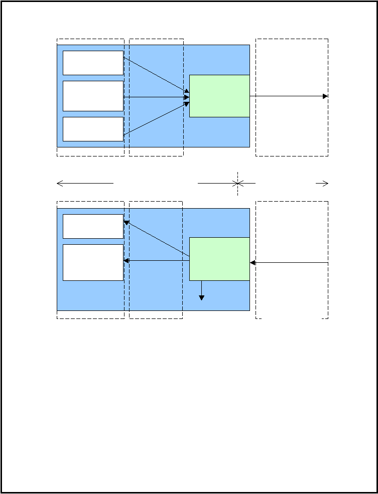 SAE J2735-Draft-Rev29 [issued: 12-11-08]
-
237 -
This is an SAE Motor Vehicle Council draft document of the DSRC committee, subject to change.
Figure 1: Example Vehicle DSRC Safety System with Safety Message Handler
Figure 1 illustrates how a MH chooses outgoing message content based on the collective requirements of
the vehicle’s safety applications. An aspect of the MH functionality not shown is the determination of
message transmission time. The simplest case is a regular message schedule with uniform content in each
message. A more complex case arises if some information is sent more frequently than others. A MH may
opt to compose messages with different content to match the specific information rate requirements of the
applications. For example, if in Figure 1 the Lane Change Warning application only requires half the
information rate as the Forward Collision Warning and Intersection Warning applications, the message
shown on the right side of the figure might be sent every other message interval, interleaved with messages
that omit the Turn Signals and Headlights data elements.
Fwd Collision
Warning
Intersection
Warning
Lane Change
Warning
Safety
Message
Handler:
Sender Side
Position, Speed, Air
Bag, Brake Status
Position, Speed, Yaw
Rate, Vehicle Trail
Position, Speed,
Yaw Rate, Air Bag,
Brake Status,
Vehicle Trail, Turn
Signals, Headlights
Position, Turn
signals, Speed,
Headlights
Fwd Collision
Warning
Intersection
Warning
Safety
Message
Handler:
Receiver Side
Turn Signals,
Headlights
IGNORED
Implementation Specific
J2735 Standard
Position, Speed,
Yaw Rate, Air Bag,
Brake Status,
Vehicle Trail, Turn
Signals, Headlights
Position, Speed, Air
Bag, Brake Status
Position, Speed, Yaw
Rate, Vehicle Trail
Communication
system
Outgoing
Message
Incoming
Message
|
 SAE J2735-Draft-Rev29 [issued: 12-11-08]
-
238 -
This is an SAE Motor Vehicle Council draft document of the DSRC committee, subject to change.
Annex C Operation with the Vehicle Basic Safety Message
1.
Application Background
The Basic Safety Message [JBK3][JBK4]in this Standard was developed based on analysis of communications
requirements for seven high-priority vehicle-to-vehicle application scenarios with significant anticipated
safety benefits. These application scenarios are:
C.1
Intersection Collision Warning
C.2
Emergency Electronic Brake Lights
C.3
Pre-Crash Sensing
C.4
Cooperative Forward Collision Warning
C.5
Left Turn Assistant
C.6
Stop Sign Movement Assistance
C.7
Lane Change Warning
The use of the Basic Safety Message in the relevant vehicle safety application scenarios is described in this
annex in Sections C-1 through C-7. These sections of the annex present vehicle safety application scenarios
and are meant to illustrate the use of the Basic Safety Message specified in this Standard, rather than to
specify or prescribe these applications or to recommend the best way to deploy these applications. It is
expected that the message sets [JBK5]in this standard will fully or partially enable the development of
additional vehicle safety applications. Illustrations of such applications may be added to this annex in
future versions of this Standard.
Future vehicle safety applications may require additional message sets, data frames and data elements that
have not yet been specified in this Standard. The intention of the DSRC Technical Committee is for these
additional elements to be identified by the Technical Committee, analyzed, specified and added to future
versions of this Standard in order to support interoperability for an increasingly diverse range of vehicle
safety applications. These additions are likely to be especially noticeable in the area of future vehicle-
to/from-infrastructure safety applications that are envisioned. Some of these will likely be vehicle safety
applications and others are likely to be public safety applications. The technical committee intends for this
Standard to support the interoperability of all these safety applications between and among vehicles from
different manufacturers and roadside infrastructure operators/manufacturers throughout the entire region of
expected vehicle travel.
The basic premise of the initial vehicle safety applications is the use of frequent broadcasts of basic
information about each individual vehicle to enhance the awareness of vehicles that are in the vicinity. The
frequency of these broadcasts is expected to at least meet the requirements of vehicle safety systems
implemented using this technology, and if possible to exceed these requirements in order to compensate for
the inherently unreliable nature of radio frequency communications.
Due to the potential cumulative effect of many vehicles broadcasting within the same local area (in
particular during heavy traffic conditions), the DSRC communication channel is likely to encounter
excessive channel loading on occasion. For this reason, it has been the focus of the technical committee to
limit the required information in these common messages to a concise set, and to provide effective coding
to minimize the size of the message payload. The common message set that was developed by the
committee to meet the requirements of the initial vehicle safety application scenarios is the
MSG_BasicSafetyMessage, which has a mandatory section (Part I) and an optional section (Part II):
Part I of the MSG_BasicSafetyMessage contains a fixed data structure comprising the information that
must be updated most frequently or which must be known to determine the meaning of the frequently-
|
 SAE J2735-Draft-Rev29 [issued: 12-11-08]
-
239 -
This is an SAE Motor Vehicle Council draft document of the DSRC committee, subject to change.
changing data. Part I is mandatory in the Basic Safety Message, and so might be broadcast more frequently
than the optional Part II. The transmission frequency of the Basic Safety Message might be chosen so that
it provides an update rate that is consistent with the scan rates for on-board vehicle safety system sensors.
Part II of the MSG_BasicSafetyMessage is optional, and so might be included in only a subset of the
messages. The additional data provided in Part II is either required less frequently by vehicle safety
applications, or is less important, or both. Part II information, when present, might vary from message to
message. Part II can be included periodically or triggered by an event or a request. Locally defined content
can be sent in Part II as well, although this requires additional definition in the ASN and XML used. [JBK6]
MSG_BasicSafetyMessage Frame, Part III, which contains additional data frames or data elements with
open-ended tags. Part III is added on an ‘as required’ basis to allow the communication of data that is not
included in Part I or Part II.
2.
Applicable documents
A detailed description of the identification and selection of the high-priority vehicle safety applications, as
well as the background descriptions of the application scenarios, are included in the “Vehicle Safety
Communications Project Task 3 Final Report: Identify Intelligent Vehicle Safety Applications Enabled by
DSRC”, published by the National Highway Traffic Safety Administration in March 2005 and publicly
available from National Technical Information Service, Springfield, Virginia 22161 (or online at
3.
Application message sequences
The repetitive broadcast of vehicle safety messages is expected to increase the range of vehicle
environmental awareness beyond the range of any on-board sensors. Each vehicle will broadcast its
relevant information frequently via the MSG_BasicSafetyMessage and receive the equivalent messages
from all DSRC-equipped vehicles in the immediate vicinity. Messages from other vehicles can then be
analyzed by on-board processors to identify impending situations that would warrant warning the driver or
initiating other actions, for example, pre-tensioning of seat belts.
4.
Application use with DSRC
Basic Safety Messages will usually be transmitted using the Wave Short Message Protocol (WSM) stack on
a pre-agreed channel, to other devices (typically other mobile on-board units (OBUs)) which have
determined to receive this type of message. It will not be necessary for a sender to advertise a service, nor
for a receiver to undertake any confirm or join operation.
Receivers are expected to process all such messages. Upon receipt, a Basic Safety Message is examined for
message content and relevance at the application layer of the protocol stack.
Basic Safety Messages are expected to be broadcast at a rate sufficient to provide a level of data quality,
including data freshness, similar to that provided by on-board sensors used for vehicle safety systems.
However, to help prevent the possibility of vehicle broadcast messages congesting a channel, the frequency
of transmissions may need to be adjusted in dense traffic environments based on speed, number of vehicles
in close proximity or other parameters (e.g., a toll plaza).
|
 SAE J2735-Draft-Rev29 [issued: 12-11-08]
-
240 -
This is an SAE Motor Vehicle Council draft document of the DSRC committee, subject to change.
In all seven of the following application scenarios, a working GPS unit
6
and a connection to the vehicle
data bus, in addition to a DSRC radio unit, are necessary to send out the correct information to, and receive
the necessary information from, other vehicles.
Annex C-1 Intersection Collision Warning
Application Description
This application warns drivers when a side-impact or straight crossing path collision at an intersection is
probable. DSRC communications can be used to allow a vehicle approaching an intersection to detect all
nearby vehicles, their position, velocity, acceleration, and turning status. The in-vehicle unit analyzes these
parameters for the other vehicles as contained in their MSG_BasicSafetyMessages and projects future
vectors for these vehicles. If this analysis determines that a collision is likely, an appropriate warning is
issued to the driver.
Flow of Events
Flow of events
1.
Vehicle “A” sends MSG_BasicSafetyMessage,
2.
Vehicle “B” receives message
3.
Vehicle “B” processes the message from Vehicle A and determines that Vehicle A’s message
is relevant (crossing road segment via map and/or heading)
4.
Vehicle “B” alerts its driver to a straight crossing path hazard.
Hardware Devices:
DSRC radio
Positional and vehicle sensors
Human-Machine Interface
Occupant
Vehicle
System
Driver
Passenger
Service
Provider
Road
Department
[JBK7]
Actors:
(What entities play
an active role in use)
X
X
Support information:
CAMP-VSC Task 3 Report, 2003
Concept of Operations
For this application, it is assumed that all identified subject vehicles would be equipped with DSRC units. It
is also assumed that messages from each vehicle would be received by conflicting vehicles on other
intersection legs, a process that might involve high transmission power or relaying techniques if the
transmitter and receiver do not have clear line of sight.
Upon receipt of each MSG_BasicSafetyMessage, the recipient needs to implement an algorithm to
determine if a crossing path conflict is present. Once a conflict is determined the vehicle could use
appropriate human machine interface (HMI) techniques aboard the vehicle to issue a warning to the driver.
6
Which is presumed to be able to provide position, velocity, and current time values for the vehicle.
|
 SAE J2735-Draft-Rev29 [issued: 12-11-08]
-
241 -
This is an SAE Motor Vehicle Council draft document of the DSRC committee, subject to change.
Sensors and Other System Needs
A map database could help to provide information about whether crossing path vehicles are in the vicinity
of an intersection. If lane resolution is possible, lane position of the crossing path vehicle can be used in
the algorithm, e.g., if a crossing path vehicle is in a left-turn pocket and it is known in advance that the left-
turn and straight-through phases are different, then the left-turning vehicle is no longer a likely threat.
Annex C-2 Emergency Electronic Brake Lights
Application Description
When a vehicle brakes hard, the Emergency Electronic Brake Light application conveys this information to
surrounding vehicles via one or more Basic Safety Messages. This application will help the driver of a
following vehicle by giving an early notification that the lead vehicle is braking hard even when the
driver’s visibility is limited (e.g. a large truck blocks the driver’s view, heavy fog, rain).
The current brake lamp goes on when the driver applies the brake. The Emergency Electronic Brake Light
application might not only enhance the range of a hard braking message but also might provide important
information such as acceleration/deceleration rate and duration. At present, brake lamps do not differentiate
level of deceleration and are only useful as far rearward as line of sight allows.
Flow of Events
Flow of events
1. Vehicle “A” sends MSG_BasicSafetyMessage, possibly with additional data associated with
the hard braking event, such as a hard-braking event flag
2. Vehicle “B” receives message
3. Vehicle “B” processes the message from Vehicle A and determines that Vehicle A’s message
is relevant (similar heading in advance of Vehicle B’s path) and a significant braking event is
occurring per the message information (e.g. deceleration, brake pressure, event flag).
4. Vehicle “B” alerts its driver to the braking event and provides some indication of braking
severity.
Hardware Devices:
DSRC radio
Positional and vehicle sensors
Human-Machine Interface
Occupant
Vehicle
System
Driver
Passenger
Service
Provider
Road
Department
Actors:
(What entities play an
active role in use)
X
X
Support information:
CAMP-VSC Task 3 Report, 2003
|
 SAE J2735-Draft-Rev29 [issued: 12-11-08]
-
242 -
This is an SAE Motor Vehicle Council draft document of the DSRC committee, subject to change.
Concept of Operation
For this application, it is assumed that the vehicle in a hard braking situation would be equipped with a
DSRC unit. It is also assumed that the message from the vehicle would be received by the following
vehicles, including any that could have a collision with the braking vehicle.
The message sender needs to have an algorithm to decide if a hard brake was performed (for example:
deceleration greater than 0.4g), and if a non-routine event message transmission is advisable. If a vehicle
determines that it is braking hard then it could inform the surrounding vehicles by sending a
MSG_BasicSafetyMessage, possibly including an optional “hard-brake” event flag. The message could be
sent at the next scheduled transmission time, or earlier, and it could use a higher priority level than the
routine broadcast of a MSG_BasicSafetyMessage.
In order to determine if a hard braking message is relevant, the listening vehicle needs to know the relative
location from which the message originated (e.g., front, rear, left, right). This can be done based on its GPS
information and the GPS information of the braking vehicle. The listening vehicle may not necessarily
inform the driver of such an event if the braking vehicle is traveling in an adjacent lane.
Sensors and Other System Needs
A map database, where available, may help to provide specific, relevant information related to current road
segments. This could allow, for example, intersection geometry or road curvature to be taken into account
when an application host vehicle evaluates the received MSG_BasicSafetyMessage to see if an alert to the
driver is necessary.
Annex C-3 Pre-crash Sensing
Application Description
Pre-crash sensing can be used to prepare for imminent, unavoidable collisions. This application could use
DSRC communication in combination with other sensors to mitigate the severity of a crash.
Countermeasures may include pre-tightening of seatbelts, airbag pre-arming, front bumper extension, etc.
Flow of Events
Flow of events
1.
Vehicle “A” sends MSG_BasicSafetyMessage
2.
Vehicle “B” receives message
3.
Vehicle “B” processes the message from Vehicle A and determines that Vehicle A’s
message is relevant and, per the message information (e.g. location, speed, heading,
deceleration, brake pressure, etc.), that trajectories of Vehicles “A” and “B” will likely intersect
imminently.
4.
Vehicle “B” automatically initiates pre-crash countermeasure(s).
Hardware Devices:
DSRC radio
Positional and vehicle sensors
Human-Machine Interface
Actors:
(What entities play an
active role in use)
Vehicle
Occupant
Service
Road
Department
|
 SAE J2735-Draft-Rev29 [issued: 12-11-08]
-
243 -
This is an SAE Motor Vehicle Council draft document of the DSRC committee, subject to change.
System
Driver
Passenger
Provider
Department
active role in use)
X
Support information:
CAMP-VSC Task 3 Report, 2003
Concept of Operations
As in most of the other vehicle safety application scenarios, DSRC communications is used to allow the
host vehicle to detect position, velocity, heading, acceleration, and control parameters for all equipped
vehicles in the immediate vicinity. The in-vehicle unit analyzes these parameters for the other vehicles as
contained in their MSG_BasicSafetyMessages and projects future vectors for these vehicles. If this analysis
determines that a collision is imminent and unavoidable, the vehicle may deploy countermeasures, such as
pre-tightening of seatbelts. This further information [JBK8]might be used for such potential purposes as
determining the need to lower the bumper on a high-profile vehicle to minimize the damage to a smaller,
lower vehicle, or to support a sensor-based decision to pre-deploy side-impact airbags if the collision vector
determination indicates an imminent side-impact.
Sensors and Other System Needs
On-board sensors, such as airbag accelerometers or radar systems, could be used to confirm the imminent
collision determination derived from the DSRC communications analysis.
Annex C-4 Cooperative Forward Collision Warning
Application Description
The cooperative forward collision warning (CFCW) system application is a vehicle-to-vehicle (V2V)
communication-based safety feature that issues a warning to the driver of the host vehicle in case of an
impending front-end [JBK9]collision with a vehicle ahead in traffic in the same lane and direction of travel.
CFCW will help drivers in avoiding or mitigating front-to-rear vehicle collisions in the forward path of
travel. The system does not attempt to control the host vehicle in order to avoid an impending collision.
Flow of Events
Flow of events
1.
Vehicle “A” sends MSG_BasicSafetyMessage, periodically
2.
Vehicle “B” receives and processes messages, and determines if Vehicle A is traveling ahead
in traffic in the same lane and direction of travel.
3.
If so determined, Vehicle “B” processes the message information further to determine the
threat level of a front-end crash with Vehicle A.
4.
Based on the threat level determined, Vehicle “B” warns its driver of the potential front-end
crash.
Hardware Devices:
DSRC radio
Positional and vehicle sensors
Human-Machine Interface
Actors:
(What entities play an
active role in use)
Vehicle
Occupant
Service
Road
Department
|
 SAE J2735-Draft-Rev29 [issued: 12-11-08]
-
244 -
This is an SAE Motor Vehicle Council draft document of the DSRC committee, subject to change.
System
Driver
Passenger
Provider
Department
active role in use)
X
X
Support information:
CAMP-VSC Task 3 Report, 2003
Concept of Operations
This application is similar to the Emergency Electronic Brake Light scenario (Annex C-2). In the
Cooperative Forward Collision Warning scenario, however, the application warns the driver when the
possibility of a collision with a vehicle in front of the host vehicle becomes likely, whereas the brake light
application simply informs the driver of the onset of “hard” braking based on an indication of braking rate.
The concept of operation of the CFCW application can be explained as follows: Every vehicle that is
equipped with DSRC will broadcast the MSG_BasicSafetyMessage, including the optional path history, at
a certain frequency (path history might be included in a subset of all MSG_BasicSafetyMessages). The
CFCW application in the host vehicle receives safety messages and uses the contents to track the state (i.e.,
position, velocity, and acceleration, etc.) of remote vehicles within its communication range. Using such
information, along with its own state and its assessment of the relevance of the target location, the host
vehicle determines the likelihood of a front-end collision with a remote vehicle ahead in its lane and
calculates the threat level. The threat level is used to further determine the appropriate warning through the
vehicle’s driver vehicle interface.
Sensors and Other System Needs
On-board sensors, such as radar or lidar systems, could be used to confirm the
[JBK10]collision
determination derived from the DSRC communications analysis.
A map database, where available, may help to provide specific, relevant information related to current road
segments. This could allow, for example, intersection geometry or road curvature to be taken into account.
Annex C-5 Left Turn Assistant
Application Description
The Left Turn Assistant provides information to drivers about gaps and speeds of oncoming cars to help
them make a left turn across traffic safely. This application warns drivers when a collision is probable if
the left turn movement is initiated.
Flow of Events
Flow of events
1.
Oncoming Vehicle “A” sends MSG_BasicSafetyMessage.
2.
Turning Vehicle “B” receives message
3.
Vehicle “B” processes the message from Vehicle A and determines that Vehicle A’s
message is relevant (crossing road segment via map and/or heading and indication of turn)
4.
Vehicle “B” alerts its driver to an oncoming vehicle hazard.
|
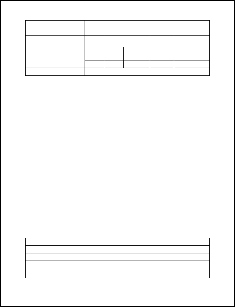 SAE J2735-Draft-Rev29 [issued: 12-11-08]
-
245 -
This is an SAE Motor Vehicle Council draft document of the DSRC committee, subject to change.
Hardware Devices:
DSRC radio
Positional and vehicle sensors
Human-Machine Interface
Occupant
Vehicle
System
Driver
Passenger
Service
Provider
Road
Department
Actors:
(What entities play an
active role in use)
X
X
Support information:
CAMP-VSC Task 3 Report, 2003
Concept of Operations
DSRC communications is used to allow the turning vehicle to detect all equipped vehicles in the vicinity.
Furthermore, it allows the turning vehicle to receive the position, velocity, acceleration, and control
parameters, among others, for potential threat vehicles. The in-vehicle unit, based upon the host vehicle’s
left turn signal initiation (and/or possibly other control parameters such as steering wheel angle or yaw rate)
constructs a predicted travel path for the host vehicle and analyzes the received parameters for the
approaching vehicles . The unit also constructs expected future travel path for these vehicles. If this
analysis determines that a collision would be likely if the left turn movement is initiated, an appropriate
warning is issued to the driver
Sensors and Other System Needs
On-board sensors to determine the host vehicle’s intent to turn left, e.g., left turn signal or other control
parameters, may be required.
A map database could help to provide information about whether vehicles are in the vicinity of an
intersection. If lane resolution is possible, lane position of left-turning and opposite path vehicles can be
used in the algorithm, e.g., if a left-turning vehicle is in a left-turn pocket and the opposite path vehicle is in
a through lane, then the left-turn warning should actuate.
Annex C-6 Stop Sign Movement Assistance
Application Description
This application provides a warning to a vehicle that is about to cross through an intersection after having
stopped at a stop sign. This may prevent collisions with traffic approaching the intersection. In particular,
this application warns drivers when a collision is probable if the indicated start-from-stop is initiated.
Flow of Events
Flow of events
1.
Vehicle “A”, starting from stop, sends MSG_BasicSafetyMessage
2.
Vehicle “B” receives message
3.
Vehicle “B” recognizes that Vehicle A’s message is relevant and, per the message
information (e.g. location, speed, heading, acceleration, throttle position, etc.), that
trajectories of Vehicles “A” and “B” will likely intersect.
|
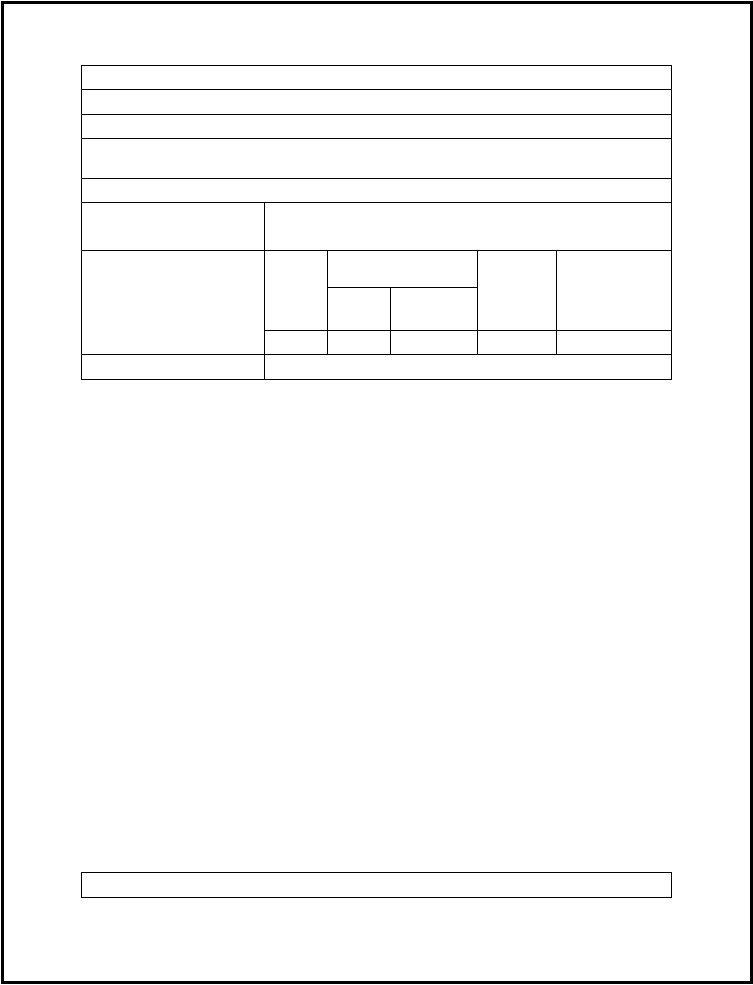 SAE J2735-Draft-Rev29 [issued: 12-11-08]
-
246 -
This is an SAE Motor Vehicle Council draft document of the DSRC committee, subject to change.
4.
Vehicle “B” alerts its driver to a straight crossing path hazard.
5.
Vehicle “B” sends MSG_BasicSafetyMessage
[JBK11]
6.
Vehicle “A” receives message.
7.
Vehicle “A” processes the message from Vehicle A and determines that Vehicle B’s
message is relevant (crossing road segment via map and/or heading)
8.
Vehicle “A” alerts its driver to a start-from-stop hazard.
Hardware Devices:
DSRC radio
Positional and vehicle sensors
Human-Machine Interface
Occupant
Vehicle
System
Driver
Passenger
Service
Provider
Road
Department
Actors:
(What entities play an
active role in use)
X
X
Support information:
CAMP-VSC Task 3 Report, 2003
Concept of Operations
DSRC communications is used to allow the stopped vehicle to be informed of the presence of other
vehicles in the immediate vicinity. The frequently broadcast MSG_BasicSafetyMessages from vehicles in
the area allow the stopped vehicle to receive the position, velocity, acceleration, and control parameters,
among others, from these vehicles. The in-vehicle unit, based upon the host vehicle’s stopped condition and
combination of release of brake and application of throttle, for example, constructs a predicted travel path
for the host vehicle and also constructs expected travel path for the other detected vehicles by analyzing
their received parameters. If the in-vehicle unit determines that a collision would be likely if the start-from-
stop maneuver is initiated, an appropriate warning is issued to the driver.
Sensors and Other System Needs
On-board sensors to determine the host vehicle’s stopped condition and combination of release of brake
and application of throttle are also needed.
A map database could help to provide information whether crossing path vehicles are in the vicinity of an
intersection. If lane resolution is possible, lane position of the crossing path vehicle can be determined and
used in the algorithm.
Annex C-7 Lane Change Warning
Application Description
This application provides a warning to a vehicle that is about to change lanes. The warning is provided in
order to avoid a collision with vehicles in the intended lane destination of the host vehicle.
Flow of Events
Flow of events
|
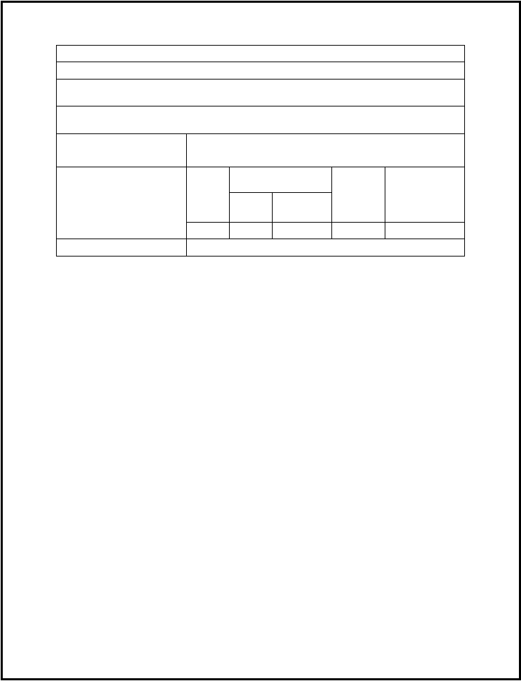 SAE J2735-Draft-Rev29 [issued: 12-11-08]
-
247 -
This is an SAE Motor Vehicle Council draft document of the DSRC committee, subject to change.
1.
Overtaking Vehicle “A” sends MSG_BasicSafetyMessage
2.
Lane-changing Vehicle “B” receives message
3.
Vehicle “B” processes the message from Vehicle A and determines that Vehicle A’s message
is relevant (by location in adjacent lane, proximity or rate of overtaking)
4.
Based upon the host vehicle’s turn signal indication and /or possibly other control parameters
like steering movements, Vehicle “B” alerts its driver to a potential overtaking vehicle hazard.
Hardware Devices:
DSRC radio
Positional and vehicle sensors
Human-Machine Interface
Occupant
Vehicle
System
Driver
Passenger
Service
Provider
Road
Department
Actors:
(What entities play an
active role in use)
X
X
Support information:
CAMP-VSC Task 3 Report, 2003
Concept of Operations
As with the other vehicle safety application scenarios in this annex, DSRC communications is used to allow
the host vehicle to detect all equipped vehicles in the immediate vicinity. As well, the lane-changing
vehicle receives the position, velocity, acceleration, and control parameters, among others, for all these
vehicles through their MSG_BasicSafetyMessages. The in-vehicle unit, based upon the host vehicle’s turn
signal and/or possibly other control parameters like steering wheel movements, constructs a potential
vector for the host vehicle and analyzes the received parameters to construct expected future vectors for
other vehicles in the immediate vicinity. If the in-vehicle unit determines that a collision would be likely if
the indicated lane change maneuver is initiated, an appropriate warning is issued to the driver.
Sensors and Other System Needs
On-board sensors to determine the host vehicle’s intent to change lanes, e.g., turn signal or other control
parameters, will also be needed.
A map database, if available, could help to provide information about whether vehicles are in adjacent
lanes. In addition, the road curvature can be taken into account when an application host vehicle evaluates
the presence of an approaching or existing vehicle in the adjacent lane.
|
 SAE J2735-Draft-Rev29 [issued: 12-11-08]
-
248 -
This is an SAE Motor Vehicle Council draft document of the DSRC committee, subject to change.
Annex D: Traveler Information Message Use and Operation
Traveler Information Introduction
Traveler Information is designed to enable broadcast advisory messages to the vehicle driver based upon
location and situation relevant information. Messages are prioritized both for delivery and presentation
based on the type of the advisory. Presentation to the driver may be in the form of text, graphics, or audio
cues.
Examples include traveler advisories (traffic information, traffic incidents, major events, evacuations, etc.)
and road signs. Traveler advisories are dynamic and temporary in nature. Conversely, road sign messages
emulate their physical counterparts and are static in nature. Differences are discussed in this document.
The message, developed by the SAE-DSRC Traffic and Traveler Information Subcommittee discussed
earlier in this standard, describes the payload of the Traveler Information Message. This Annex describes
how[CH12]
[RS13]the On-Board Unit (OBU) will receive traveler information as well as how an OBU could
utilize the data prior to presentation to the driver[RS14]. The format and mode of the presentation to the
driver is left to the developer.
Traveler Information Packet Structure
The following text describes the format of a packet containing multiple individual advisories or road signs.
(Refer to Figure 1: Packet Format, on the following pages)
Packet Structure
Multiple traveler advisories or road signs may be packaged into a single packet for transmission. However,
it is recommended practice not to mix advisories and road signs within the same packet since road signs are
essentially stable whereas advisories require frequent updates. [CH16]
Each packet has a unique Packet ID. If a vehicle’s OBU has processed a packet with a particular ID, it can
then ignore subsequent packets with that same ID, updated packets will have a different ID. The
recommended Packet ID structure is an octet string which is a combination of an agency identifier in the
most significant byte and timestamp in the subsequent bytes. An example of this recommended Packet ID
structure in shown below[CH18]
.
packetID
OCTET STRING (SIZE(9)),
-- PacketID (9-Byte ID)
--Recommended packetID structure
Byte 1
Bytes
2-3
Byte 4
Byte 5
Byte6
Byte7
Bytes 8-
9
Agency
ID
Data Frame Header
All individual message (data frame) headers are of a common format. However, individual messages are
either of type “advisory” or “road sign”. If it is an advisory, the message ID consists of a 2-byte Advisory
Number. This Advisory Number can be used to connect to additional message content transmitted in the
ATIS message format over the TCIP/IP stack, if available. If it is a road sign, the message ID is a
7
Here OBE is used, elsewhere OBU is used, pick one and stick with it.
|
 SAE J2735-Draft-Rev29 [issued: 12-11-08]
-
249 -
This is an SAE Motor Vehicle Council draft document of the DSRC committee, subject to change.
combination of 3D position, direction and an MUTCD code. In addition to a message ID, the header
contains a start time, duration time, and priority. This allows the advisory style of message to be similar to
Dynamic Message Sign (DMS) content or to ATIS event message content (and therefore dynamic),
whereas currently a road sign is typically painted (and therefore static).
Data Frame Valid Regions
Up to 8 valid regions may be used to geographically define where each message is useful to the driver.
Multiple regions are used to describe precise segments of roadway where the message applies, such as east
and west bound lanes approaching an intersection or interchange.
Data Frame Content
All advisory content consists of multiple ITIS code/text fields and an[CH20]
optional URL to images or
additional information.
The format of road sign content depends on the MUTCD code for the sign. Existing formats for road sign
content include – speed limit, work zone warning, and exit services. Additional content formats will be
defined in further editions of this standard. These future formats will couple similar types of road signs
into broad categories. Each broad category of road signs will share a common content format. The general
format follows the established rules for using ITIS text and phrases, but with minor presumptions or
restrictions for DSRC needs.
A provision also exists for a generic road sign category. The list of valid MUTCD codes
(DE_MutcdTagList) includes a “generic” value. All generic road sign content also allows a text field and
an optional URL[CH21]
9
pointing to additional information. In general free text is avoided in the DRSC
message set work, but here limited means are provided to allow[RS22] some free text (often needed for local
street and place names).
8
DCK: Small terminology issue to resolve here. The term “message”: is being used to describe both the
“inner” message and the “outer” (up to sets of 8) message. Need to address this, and ID vs Time issues.
9
Bring up the concept of a base URL/URI to be found in another periodically sent “background”
message here. Will need yet another short annex to further develop this concept. Does the committee want
to support NTCIP “MULTI” strings from CMS/VMS signs here as well?
|
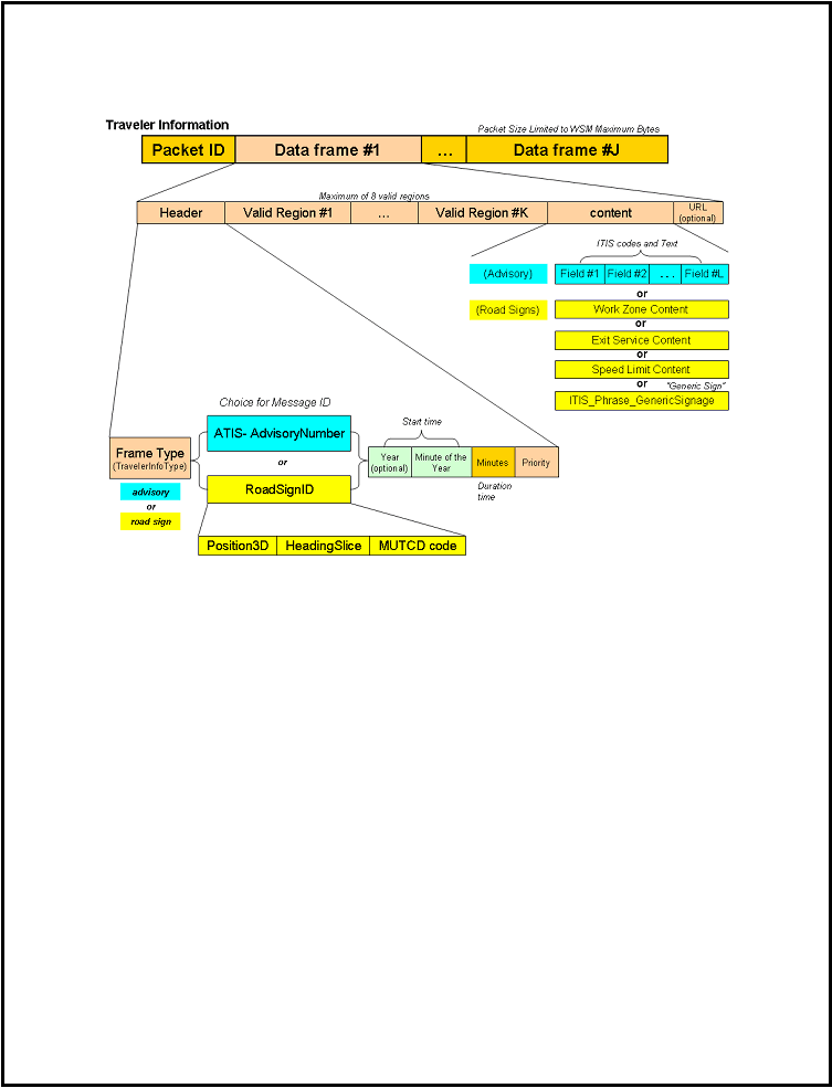 SAE J2735-Draft-Rev29 [issued: 12-11-08]
-
250 -
This is an SAE Motor Vehicle Council draft document of the DSRC committee, subject to change.
Packet Format Diagram
Figure 2: Packet Format
The ASN presention of the message ( TravlerIformaiton ) can be found in seciton 5 of document (along
with its XML form) .
Traveler Advisory Example
This sample packet contains two data frames, and they are both advisories that indicate traffic is reduced to
one lane. The first advisory has two circular activation regions, begins on January 10th 2008, lasts for 30
days, and warns drivers to use the right lane. The second advisory has one circular activation region,
begins on January 10th 2008, lasts for 5 days, and warns drivers to use the left lane.
Both advisories have the optional LRMS-type location populated. Some vehicles may have the capability
to present this information to the driver. Some vehicles with on-board maps may also be able to use this
data to determine the affected geographic location of the advisory.
Both advisories also support the optional off-board URL for a descriptive image. Again, some vehicles
may be able to retrieve this image through an alternative mechanism – WiMax, WiFi, Cellular modem, etc.
or by way of the TCIP/IP stack over DSRC.
|
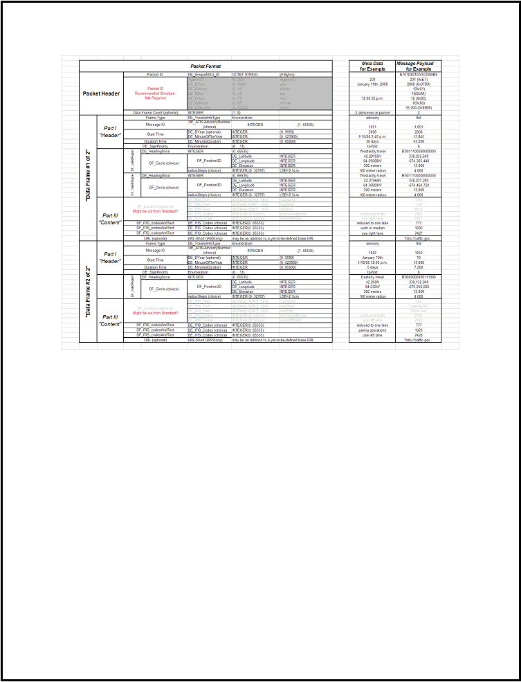 SAE J2735-Draft-Rev29 [issued: 12-11-08]
-
251 -
This is an SAE Motor Vehicle Council draft document of the DSRC committee, subject to change.
Figure 3: Travel Advisory Example
|
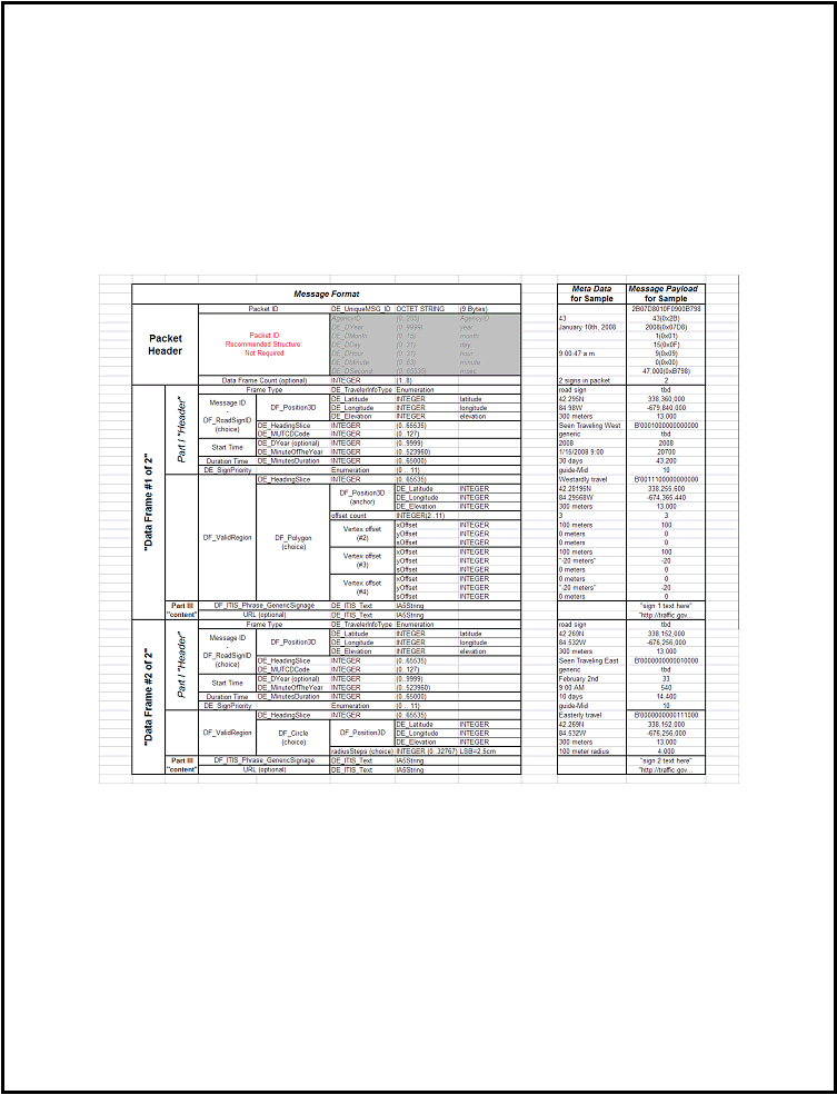 SAE J2735-Draft-Rev29 [issued: 12-11-08]
-
252 -
This is an SAE Motor Vehicle Council draft document of the DSRC committee, subject to change.
Road Sign Example
This sample packet contains two generic road signs. The first road sign has a single valid region defined
by a four-point polygon. The second road sign’s valid region is a circle.
The basic content of the signs is the text string included in their “content” sections.
The signs also contain the optional off-board URLs for descriptive images. Some vehicles may be able to
retrieve these images through an alternative mechanism – WiMax, WiFi, Cellular modem, etc., or by way
of the TCIP/IP stack over DSRC.
Figure 4: Road Sign Example
Application and Use with DSRC
Network User
Network Users generate individual advisory or road sign messages. Network users need to assign unique
identifiers or “Advisory Numbers” to advisories. Road signs, however, are intrinsically identified by their
location, direction and MUTCD code. The individual messages are then propagated into the backhaul
network and eventually to the Road Side Unit (RSU). It is expected that this transmission will use the
defined XML message formats of this standard and TCIP/IP for such transfers.
|
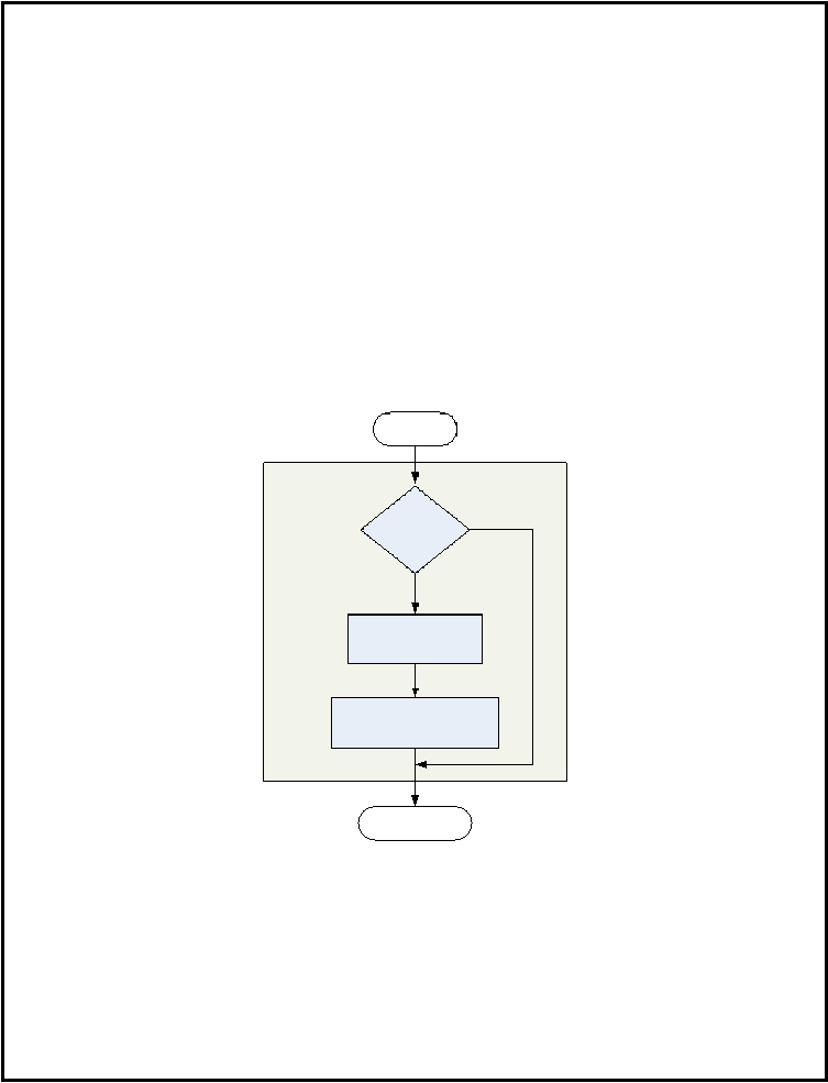 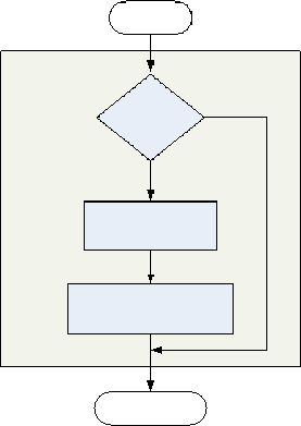 SAE J2735-Draft-Rev29 [issued: 12-11-08]
-
253 -
This is an SAE Motor Vehicle Council draft document of the DSRC committee, subject to change.
Network User
?
RSU
Individual advisories and road signs are combined together into packets, which must meet the
maximum[CH23]
size limitation of Wave Short Messages (WSM). Unique Packet IDs are assigned to these
combinations of specific messages. If any individual messages are altered or added to a packet, a new
packet is formed with a new Packet ID.
RSU
?
OBU Over-the-Air Traffic
The flow of traveler advisory and road sign packets is one-way from the RSU to the vehicle (OBU). All
traffic is transmitted via WSM. Very high priority packets can be transmitted over the Control Channel
(CCH). However, most packets will typically be transmitted over a Service Channel (SCH). A packet is
transmitted on the appropriate channel during the corresponding time slice. Depending on priority of the
packet, it may be repeated multiple times per time slot to ensure delivery.
Handling Repeated Packets
The Packet ID is used to determine if any new traveler information messages have been received by the
vehicle. If the data frames for a particular packet have already been stored locally, then subsequent receipts
of the packet can be ignored. The general flow of receiving a packet is shown below.
Handle Packet Receipt
Is Packet ID
already in
Data Store
?
Store Packet ID
In Data Store
Handle Packet Contents
No
Yes
New Packet is
Received
Wait for Receipt of
New Packet
Figure 5: Handle Packet Receipt
|
 SAE J2735-Draft-Rev29 [issued: 12-11-08]
-
254 -
This is an SAE Motor Vehicle Council draft document of the DSRC committee, subject to change.
Handling Newly Received Data Frames
Packets may contain geographically overlapping areas of advisories or road signs. As a result, a new
packet
[RS24]
can be received that contains advisories or road signs already received by the vehicle. If a
received Sign ID or Advisory ID is not a match to anything on the vehicle, then it is new and should
[RS25]be[CH26]
stored
10
[CH27]
. If there is a match for this ID, then the Start Time needs to be checked. If
the stored Start Time is newer, then this received data frame is outdated. Likewise, if the stored Start Time
is the same, then it is repeated. In both cases, the received data frame can be discarded. However, if the
stored Start Time is older, then the received advisory or sign is updated. The old one is deleted, and the
received one is stored in its place.
The following flowchart displays how each data frame can be parsed when receiving a new packet.
10
DCK: Is this strictly correct, if traveling in the other direction can not content be dropped?
|
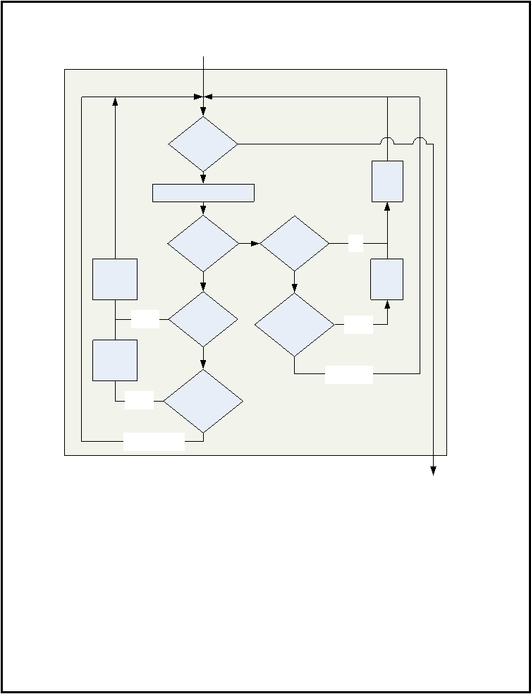 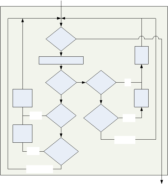 SAE J2735-Draft-Rev29 [issued: 12-11-08]
-
255 -
This is an SAE Motor Vehicle Council draft document of the DSRC committee, subject to change.
Handle Packet Contents
Read next Data Frame
More
Data Frames in
packet
?
Is
Sign ID in
data
store
?
No
Yes
Yes
Is
“Start Time”
Newer than Data
Store
?
Yes
No
No
New
Sign
Updated
Sign
Sign
Or
Advisory
?
Store
New
Sign
sign
Repeated or
Outdated Sign
Is
Advisory ID in
data
store
?
Is
“Start Time”
Newer than Data
Store
?
advisory
Delete
Old
Advisory
Store
New
Advisory
New
Advisory
Updated
Advisory
No
Yes
Yes
No
Delete
Old
Sign
Repeated or
Outdated Advisory
Figure 6: Handle Packet Contents
Replacement Policy for Locally-Stored Messages
Pruning Messages by In-vehicle Housekeeping
Housekeeping will need to be performed on the vehicle to delete stale messages. The most obvious method
is to delete messages with an “Duration Time” that has been exceeded. However, the OBU will have
limited physical memory and will likely need to employ some additional type of replacement policy when
the memory limit is reached. This may be based on priority, heading, distance from vehicle, FIFO, start
time, etc.
|
 SAE J2735-Draft-Rev29 [issued: 12-11-08]
-
256 -
This is an SAE Motor Vehicle Council draft document of the DSRC committee, subject to change.
Updated Messages from Network
If a network user needs to update a message, it issues it again with the same message ID[RS28][CH29] but a
more recent start time. Note that a message ID is either an Advisory ID or Roadsign ID as shown
previously in Figure2. This allows for updated traveler information. A weather advisory issued in the
morning[RS30][CH31]
may need to be updated later as conditions change.
Deleting Messages as Directed by Network User
There is also a mechanism for the Network User to delete, or recall, messages that have already made it to
the vehicle. It exploits the in-vehicle housekeeping algorithm to enable a network-directed deletion. An
updated message is sent where the Duration Time has already passed (or is set to zero). The updated
message will replace the old one in the vehicle’s data store. Subsequently, it will be purged by the local
housekeeping algorithm for being expired. A work zone warning issued early in the morning may need to
be deleted if the construction schedule is delayed.
Vehicle Power-Up Events
Need some more text here to deal with the user case of vehicle power down-purge and then a new power
up. Need to also discuss what happens when the power up occurs inside the footprint of these messages
being sent (rather then when outside) and recommend an algorithm to cope with that event.
It[RS32] is advised that current
[RS33] messages be stored when the engine is stopped. Following engine start
old messages can then be purged.[CH34]
Presentation of Signs & Advisories in Vehicle
The specific presentation of road signs and traveler advisories is dependent upon vehicle manufacturer
HMI guidelines, display capabilities, etc. Some vehicles may only be capable of presenting a subset of the
message content. HMI design is out of scope for this document. However, three message attributes are
universal [RS35][CH36]
– location, direction, and time. To ensure only pertinent information is presented to
the driver, all messages have a physical region, direction of travel and timeframe in which they are valid.
Valid Time
All messages have a valid time which begins at the Start Time and ends at this point in time plus the
Duration Time[RS37] for[CH38]
that message. Advisories may exist for periods of time ranging from
minutes to hours to many days, and even years of duration in the case of planned construction. Physical
road signs exist twenty four hours a day and may be unchanged for years. Thus, during their valid time,
most road signs will be valid twenty-four hours a day. This does not imply that they are valid indefinitely.
When their expiration time is reached, they become invalid and are consequently purged from the OBU.
Exit service signs can contain a service provider with limited operating hours. The entire sign may be valid
twenty-four hours a day, but individual services can be presented to the driver during normal operating
hours.
Valid time is transmitted in the message with a start time element. It is expressed in a day of the year
(0..366) and the minute of the day (0..1440) format (as well as an optional year and other time elements)
which is part of the startTime. The duration (expressed in a number of minutes from the startTime), allows
a span of 45 days with a resolution of 1 minute, (as well as longer standardized durations lengths like one-
year). OBU devices can easily combine these elements to determine is a specific message is still valid.
12
DCK: Extensive rework of time used here to save a few bytes and make the format tighter. Functional
requirements and abilities are the same but need committee review to confirm.
|
 SAE J2735-Draft-Rev29 [issued: 12-11-08]
-
257 -
This is an SAE Motor Vehicle Council draft document of the DSRC committee, subject to change.
Traveler advisory are continually active during their valid time, and they should always be considered for
presentation when they are active. The sign priority data element may be of value in determining this.
|
 SAE J2735-Draft-Rev29 [issued: 12-11-08]
-
258 -
This is an SAE Motor Vehicle Council draft document of the DSRC committee, subject to change.
Valid Region
The validity of a sign or advisory can be evaluated spatially using its valid regions. There are three types of
regions – circular, polygons and shape points. Both are described below. Physically being within the area
described by the region is not enough to make a message valid for display. A vehicle must enter the
region with the proper heading. Heading is described by dividing a range of 360 degrees into 16 different
segments (each of which are 22.5° wide) and can be combined to define the required heading of the vehicle
when entering the region.
13
ASN.1 Representation:
ValidRegion ::= SEQUENCE {
direction HeadingSlice,
-- field of view over which this applies,
extent Extent OPTIONAL,
-- the spatial distance over which this
-- message applies and should be presented
-- to the driver
area CHOICE {
shapePointSet ShapePointSet,
-- A short road segment
circle Circle
-- A point and radius
}
}
Circular Region
A circular region can be used to encompass an entire intersection or a point along a roadway segment. The
region below describes a two-way stop at an intersection. The blue circle describes the entire geographic
area where the sign may be valid. However, the stop sign is only valid when entering from the direction of
Car #1 and Car #2. To constrain the message, we use the direction field (if these directions can be taken as
being east-west then a value of 0x[RS39]8181[CH40]
would be used). When the vehicle enters a region, the
direction field is checked against the vehicle heading. If it does not match, the sign is not valid. This check
is only performed upon entering the region. Thus, Car #3 will not be presented with the stop sign even if it
turns at the intersection.
A circular region is the simplest region. It works well on small areas like this simple intersection. It can
also be effective for very large areas. A weather advisory for the entire Detroit Metropolitan area can
utilize a large circular region that is valid for all directions of travel.
14
ASN.1 Representation:
Circle ::= SEQUENCE {
center Position3D,
raduis CHOICE {
raduisSteps INTEGER (0..32767),
-- in unsigned values where
-- the LSB is in units of 2.5 cm
miles INTEGER (1..2000),
13
DCK Note: This needs a bit more work because your use of “view angle” ( a “vehicles direction while
facing the sign”) seems to also be part of the use/discard determination. Upon further reflection, I am not
sure that element (or the single position one) is really needed, as your region definition seems to handle it
well, and can do the same sign displayed in multiple approaches anyway (such as the same signage on east
and west bound lanes) Unless the actual sign location is needed, can probably drop these elements.
14
This suggests a radius of 100 miles or more, but with less precision on the edge. Perhaps we use a
CHOICE here, either the map element (2.5 cm LSB), or a element with units of “miles” or some such.
|
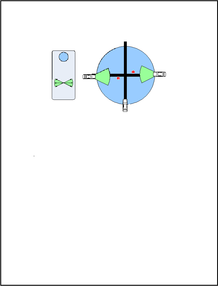 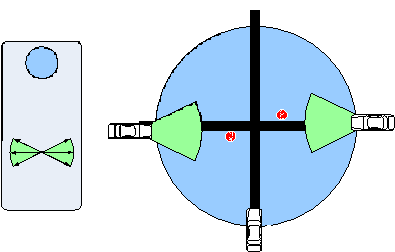 SAE J2735-Draft-Rev29 [issued: 12-11-08]
-
259 -
This is an SAE Motor Vehicle Council draft document of the DSRC committee, subject to change.
km INTEGER (1..5000)
} --# UNTAGGED
}
1
2
3
Valid Region
Valid Range
of Heading
Figure 7: Circular Region
Polygon Region
While the circular region is simple, its shortfall is that it is too inclusive. In the example below, exit
services (gas, food, and lodging) are to be advertised at an exit ramp on an interstate highway. If a large
circular region was used, vehicles on Crescent Blvd would also present the exit service message. Even
with the use of the direction field, access roads would still erroneously display the message. In this
example, eight points are used to display a polygon region that encompassed I-96 but excludes Crescent
Blvd.
DCK Note: Chris: this does the exact same thing that the current draft allows in the shape point set of the
valid region (except that the anchor need not be part of the point set), and its not really a closed surface (a
polygon). You don’t need it. Did you really want to support a true polygon (a collection of connected point
to form a closed surface)? Made no changes in the std from this.
ASN.1 Representation:
[CH41] Polygon ::= SEQUENCE { -- Polygon Description (limited to 12
vertices)
anchor
position3D,
--anchor of polygon
numOffsets
Integer(0..32),
offsets
SEQUENCE (SIZE(1..32)) OF
Offsets
--each offset describes the next in-order
--vertex around the polygon as referenced
--to the anchor point.
}
Offsets ::= SEQUENCE {
xOffset
INTEGER (-32768..32767),
-- long offset in meters
yOffset
INTEGER (-32768..32767), -- lat offset in meters
sOffset
INTEGER (-32768..32767) OPTIONAL -- elev offset in meters
},
|
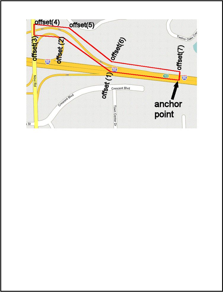 SAE J2735-Draft-Rev29 [issued: 12-11-08]
-
260 -
This is an SAE Motor Vehicle Council draft document of the DSRC committee, subject to change.
Figure 8: Polygon Region
Shape Point Set Region
An alternate form of valid region is the shape point. It allows a spline-like representation of a road
segments using the same concepts developed for DSCR map fragments and is intended to tightly bind the
region to the contour of a particular road. The described segments use the node list to efficiently describe
the contour of the roadway center line as well as any changes in width and elevation (optional elements
used only when needed).
ASN.1 Representation:
ShapePointSet ::= SEQUENCE {
anchor Position3D,
laneWidth LaneWidth OPTIONAL, -- initial width
nodeList NodeList, -- path details of the lane and width
...
}
where:
NodeList ::= SEQUENCE (SIZE(1..64)) OF Offsets
Offsets ::= SEQUENCE {
xOffset INTEGER (-32767..32767),
yOffset INTEGER (-32767..32767),
zOffset INTEGER (-32767..32767) OPTIONAL,
width LaneWidth OPTIONAL
-- all in signed values where
-- the LSB is in units of 1.0 cm
}
|
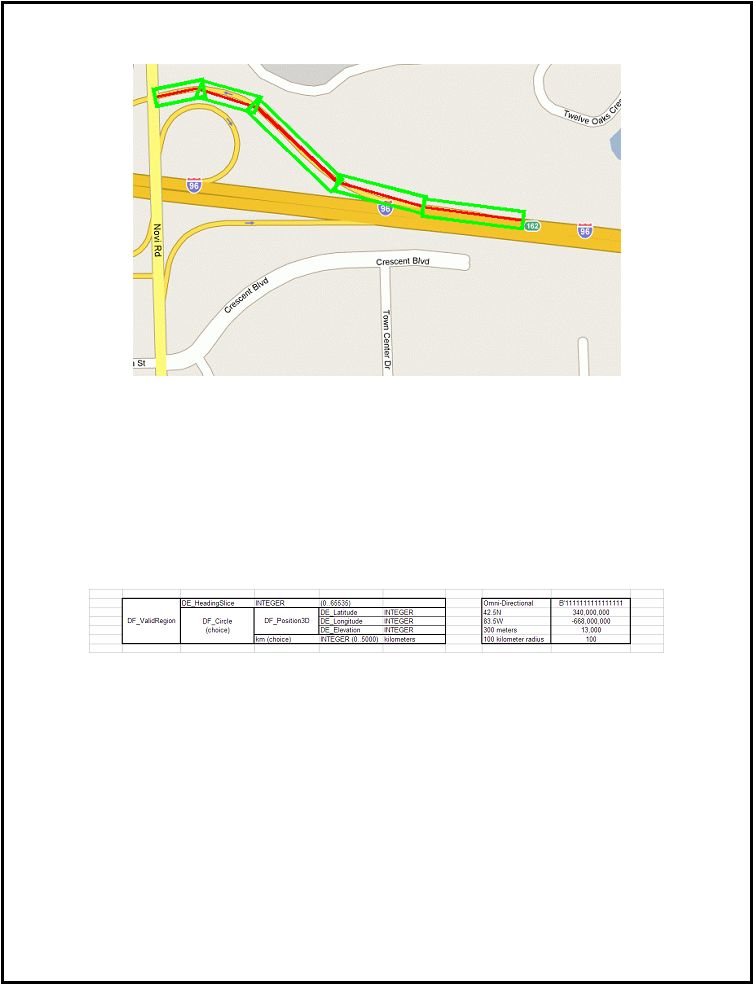 SAE J2735-Draft-Rev29 [issued: 12-11-08]
-
261 -
This is an SAE Motor Vehicle Council draft document of the DSRC committee, subject to change.
Figure 9: Shape Point Region
Extremely Large Regions
Circular regions should be used to designate extremely large areas. A circle can be set as large as an entire
state or county. Setting the DE_HeadingSlice to 0xFFFF ensures that any vehicle within the region will
consider the corresponding traveler information to be active.
In the following example, a weather advisory needs to be issued that is relavent to the entire southeastern
portion of Michigan. The following table represents a circular region centered around Green Oak,
Michigan with a radius of 100 kilometers. The region is valid for any direction of travel. Figure 10
graphically demonstrates the region.
|
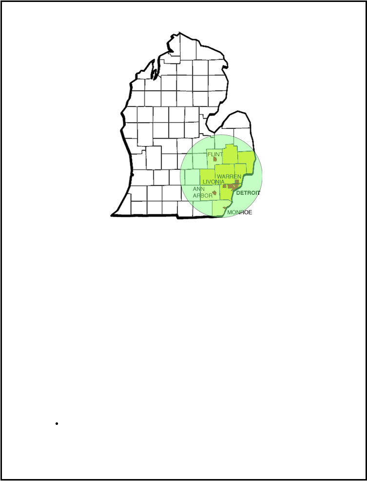 SAE J2735-Draft-Rev29 [issued: 12-11-08]
-
262 -
This is an SAE Motor Vehicle Council draft document of the DSRC committee, subject to change.
Figure 10: Large Weather Advisory
Annex E Traffic Probe Message Use and Operation
Probe Data Introduction
Probe Data is comprised of vehicle attribute and sensor data that is collected and sent from a vehicle OBU
to a local RSU. This data will be used to ascertain real time road, weather, and traffic conditions. The post-
processed data will be used to advise vehicles approaching the area of current conditions and suggest
appropriate action. This data is collected autonomously as vehicles are traveling along the roadway system
and sent to an RSU when applicable. The probe message developed by the SAE-DSRC Traffic and
Traveler Information Subcommittee discussed earlier in this standard, describes the payload and format of
the Probe Data Message. This Annex describes when the OBU should collect Probe Data from the
vehicle’s internal modules/sensors as well as when and how an OBU should send the data.
Probe Message Structure
A
Probe Message
is transmitted from a vehicle to a RSU, which contains several snapshots, as well as the
standard J2735 message header information, that is a PSID and a PSC. That is:
A Provider Service Identifier (PSID) a number that identifies a service provided by an application
and
|
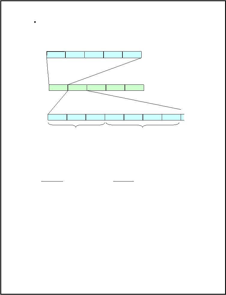 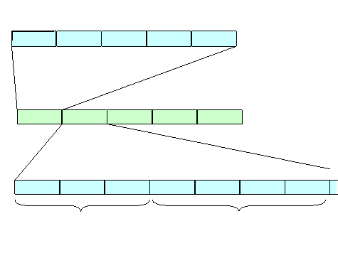 SAE J2735-Draft-Rev29 [issued: 12-11-08]
-
263 -
This is an SAE Motor Vehicle Council draft document of the DSRC committee, subject to change.
A (Provider Service Context (PSC) which is a field associated with a PSID containing
supplementary information related to the service
The simplified structure of a probe message and snapshots is illustrated below.
Header
Snapshot1
Snapshot2
Snapshot3
Snapshot4
Lat
Long
Time
PSID
PSC
Lat
Long
Time
Temp ID
Wipers
Brakes
…
Probe message standard Header
Probe message
Snapshot
Vehicle Data Elements
Snapshot Header
Figure 11 Probe Message and Snapshots
The current allowed vehicle data elements that are included in the probe snapshot are listed below. For
description, ranges, formats and units see the definition provided in Sections 7 and 8 earlier in the
standard. The message structure allows additional data elements as technology changes in vehicles and as
the standard is revised.
Data Concept
Formal Name
1.
Acceleration
2.
Acceleration Confidence
3.
Ambient Air Pressure
4.
Ambient Air Temperature
5.
Antilock Brake Status
6.
Brake Applied Pressure
7.
Brake Applied Status
8.
Brake Boost Applied
9.
Coefficient Of Friction
10.
Date
11.
Driving Wheel Angle
12.
Elevation
13.
Exterior Lights
14.
Heading
15.
Heading Confidence
16.
Latitude
17.
Longitude
18.
Obstacle Direction
19.
Obstacle Distance
|
 SAE J2735-Draft-Rev29 [issued: 12-11-08]
-
264 -
This is an SAE Motor Vehicle Council draft document of the DSRC committee, subject to change.
20.
Positioning confidence
21.
Probe Segment Number
22.
Rain Sensor
23.
Speed
24.
Speed Confidence
25.
Stability Control Status
DE_StabilityControlStatus
26.
Steering Wheel Angle Rate Of Change
27.
Steering Wheel Angle
28.
Steering Wheel Angle Confidence
29.
Sun Sensor
30.
Time
31.
Time confidence
32.
Tire Location
33.
Tire Pressure Threshold Detection
34.
Tire Pressure
35.
Traction Control State
36.
Vehicle Type
37.
Vertical Acceleration
38.
Wiper Rate
39.
Wiper Status Front
40.
Wiper Status Rear
41.
Yaw Rate
42.
Yaw Rate Confidence
Application and Use with DSRC
The messages in this application are transmitted using the Wave Short Message protocol (WSM) stack in a
single attempt unicast mode on a Service Channel (SCH) determined by the Roadside Unit (RSU) that has
signaled its ability to receive this type of message (based on PSID value and running a suitable
application). Upon reception of such messages they are examined for content and relevance regardless of
the senders ACM.
This is a provider application that employs a Wave Basic Service Set (WBSS) announced by the RSU as
per IEEE 1609.4 Clause 5.3. A confirm-before-join operation is not required by the application in order to
join and/or send Probe Data snapshots. When the application receives a Wave Management Entity (WME)
notification (indicating a WBSS has been joined) from the (WME), it will request access to the WBSS to
send all available snapshots.
This application shall transmit its messages using a PSID of 5, as defined by IEEE 1609.4 or its successors,
and a PSC of 3. Probe Data is a one-way communication stream, vehicle-to-RSU, with no
acknowledgements sent back to the vehicle by the RSU.
Probe Snapshot Generation
A Probe Data Message consists of a series of Probe Data Snapshots taken autonomously as the vehicle
travels. In the absence of any overriding probe management messages (discussed later) snapshots are
generated in three manners:
Periodically – at intervals based on vehicle movement between RSUs
Event Triggered – these occur when the state of certain vehicle status elements change
Starts and Stops – these occur when a vehicle starts moving and stops moving
These snapshots consist of all probe data elements that are available on the vehicle along with the time and
location when each snapshot was taken. Not all vehicles will support all probe data elements when the
|
 SAE J2735-Draft-Rev29 [issued: 12-11-08]
-
265 -
This is an SAE Motor Vehicle Council draft document of the DSRC committee, subject to change.
DSRC system is first launched therefore, if a vehicle does not have the ability to send a certain element, it
should not send any reference to that element.
The specific encoding of data elements sent in snapshots follows the ASN and XML definitions provided
previously. The possible elements to be sent are enclosed in a simple CHOICE statement, followed by the
individual selected elements. When more than one element is required to be sent, i.e. a data frame (as in
the case of selecting a specific wheel and then providing data about it) the normal tagging rules are still
followed. The net effect of this over the air is typically a tag byte followed by a length byte, followed by
the data itself.
Periodic Snapshots
In order to obtain ubiquitous coverage nationwide, periodic snapshots are intended to distribute snapshots
between RSUs. To do this, the default method for the periodic snapshots is designed to space the snapshots
at regular intervals between RSUs.
The default method for generating periodic snapshots is to use time and the vehicle’s current speed to
linearly space the intervals between snapshots. Although the method could use distance, the arguments for
distance depend on uneven flow when incidents occur however, most flow occurs when there is no
incidents and thus using time as the default will provider more uniform distribution of snapshots. As
vehicle speed increases, the snapshot interval increases. This results in more widely spaced snapshots at
higher speeds and closer spaced snapshots at lower speeds. This approach is used because in general RSUs
will be further apart on higher speed roads.
The following assumptions were used to determine the default interval between snapshots:
For the rural case at 60 mph (26.8 m/s), the RSU spacing is 10 minutes, or 600 seconds. When
dividing this time by 30 snapshots it results in a snapshot interval of 20 seconds.
For the urban case at 20 mph (8.9 m/s), RSU spacing is 2 minutes and the trip between RSUs
would take 120 seconds or a snapshot interval of 4 seconds.
Thus the snapshot interval is:
4 seconds if speed is
= 20 mph and
20 seconds if speed is
= 60 mph
Between 20mph and 60 mph a linear spread of snapshot intervals would be used, this is achieved by using
the speed when a snapshot is taken to set a timer to count down to the next snapshot.
The exception to the above method is that periodic snapshots do not get collected after the vehicle is
stopped (see below under starts and stops).
An implementation of the message recording loop is shown in the figure below.
|
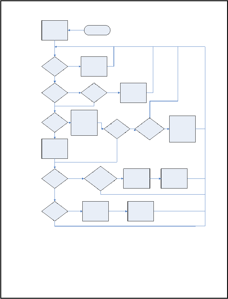  SAE J2735-Draft-Rev29 [issued: 12-11-08]
-
266 -
This is an SAE Motor Vehicle Council draft document of the DSRC committee, subject to change.
Start
Initialize Variables
Probe Data
Event
Occurred
?
Record Event
Snapshots
(
Message Writing
Procedure
)
Y
stopflag
=
1
?
v
>
vstart
?
Y
Record Start
Snapshots
(
Message Writing
Procedure
)
Stopflag
=
0
Y
V
=
0
?
If tv
0
_
last
=
0
then tv
0
_
last
=
t
ELSE
(
tv
0
=
tv
0
+
(
t
-
tv
0
_
last
)
AND tv
0
_
last
=
t
)
tv
0
>
Tstopdelay
?
Record Stop
Snapshots
(
Message Writing
Procedure
)
Tstopmsg
=
t
Stopflag
=
1
Probe
Management
Active
?
Y
Y
(
t
-
tp
)
>
Tp
(
v
)
?
AND Stopflag
=
0
((
t
-
tp
)
>
tpma
(
v
)
?
OR
(
d
-
dp
)
>
dpma
(
v
)
?
)
AND Stopflag
=
0
Record Periodic
Snapshot
(
Message Writing
Procedure
)
tp
=
t
dp
=
d
Record Periodic
Snapshot
(
Message Writing
Procedure
)
tp
=
t
dp
=
d
Y
Y
Y
Definition of Variables
:
v
=
current velocity
t
=
current time
d
=
current distance
dp
=
distance at last periodic message recording
stopflag
=
bit indicating whether vehicle stopped
(
1
=
stopped
)
tp
=
time of last periodic message recording
tv
0
=
amount of time
,
in seconds
,
vehicle speed has been
0
mph
?
tv
0
_
last
=
time in ms since the last V
=
0
evaluation
Stopflag
=
0
AND
t
-
tstopmsg
>
Tstop
tv
0
=
0
tv
0
_
last
=
0
N
N
N
N
N
N
N
N
N
Y
Definition of Parameters
:
Dpma
(
v
) =
vector of distances for periodic message recording from
probe management
Tp
(
v
) =
vector of times for periodic message recording
(
function of
velocity
.
Tpma
(
v
) =
vector of times for periodic message recording from probe
management
Tstop
=
length between stop messages when vehicle stopped
(
15
s
)
Tstopdelay
=
delay time at v
=
0
before observing vehicle stop
(
5
s
)
Vstart
=
minimum velocity to observe vehicle start
|
 SAE J2735-Draft-Rev29 [issued: 12-11-08]
-
267 -
This is an SAE Motor Vehicle Council draft document of the DSRC committee, subject to change.
Figure 12 - Message Recording Loop
While it is recognized that RSU spacing will vary from these assumptions, traffic engineers will have the
ability to actively manage the collection of probe data by changing the snapshot interval parameters for
RSUs in their purview. This management process is defined later.
Event Triggered Snapshots
Event triggered snapshots are triggered by change in vehicle status elements, either a state change (e.g.,
from off to on) or when a value exceeds a specific threshold or undergoes a transition. The purpose of
event triggered snapshots is to gather data on occurrences in the vehicle that are transitory by nature. An
example of an event driven device is traction control switching from off to on. Multiple activations of
traction control at adjacent locations could be used to indicate the location of a slippery road section.
Starts and Stops Snapshots
Snapshots are also generated by stops and starts. Start and Stop events are defined as the following:
A Stop is when there is no movement for a threshold stop time (default stop time threshold = 5
seconds) and no other stops have occurred within another threshold time (default last stop
threshold time = 15 seconds). The latter being intended to prevent multiple counts when cars
creep forward.
A Start is when the vehicle speed exceeds a threshold (default start speed threshold = 10 mph (4.5
m/s)).
As noted previously, no snapshots are taken after a vehicle has experienced a stop event until the vehicle
experiences a subsequent start event.
Starts and stops are useful indicators in a variety of traffic flow measures including incident detection and
clearance and traffic signal operational measures such as cycle failures – where the queue does not
dissipate in the first green phase.
Message Transmission Order
When a vehicle encounters an RSU that advertises the application using a PSID of 5 and a PSC value of 3,
the OBU will send a single Probe Data Message Set, comprised of several individual snapshots, on the
Service Channel indicated by the RSU. Snapshots are sent to the RSU as part of a probe message in the
following order:
1)
Event triggered snapshots are first in the transmission queue from the OBU to the RSU. Since
these often relate to specific adverse conditions that are of interest to traffic operations, these are
considered more critical than the other types of snapshots.
2)
Stops and starts triggered snapshots are second and are needed to provide finer information on
incidents and the various dynamic parameters concerning the traffic flow.
3)
Periodic snapshots are third, oldest first.
The snapshots are queued into groups of four per message, apart from when PSN changes cause a new
message. Messages with start and stop snapshots and/or periodic snapshots should be composed of
snapshots with the same PSN (Probe Segment Number as defined below). Different PSNs should be in
different messages. All of these messages are then sent as a set. Following transmission, all snapshots
including non-transmitted snapshots in the buffer are purged. An implementation of the message transmit
loop is shown below.
|
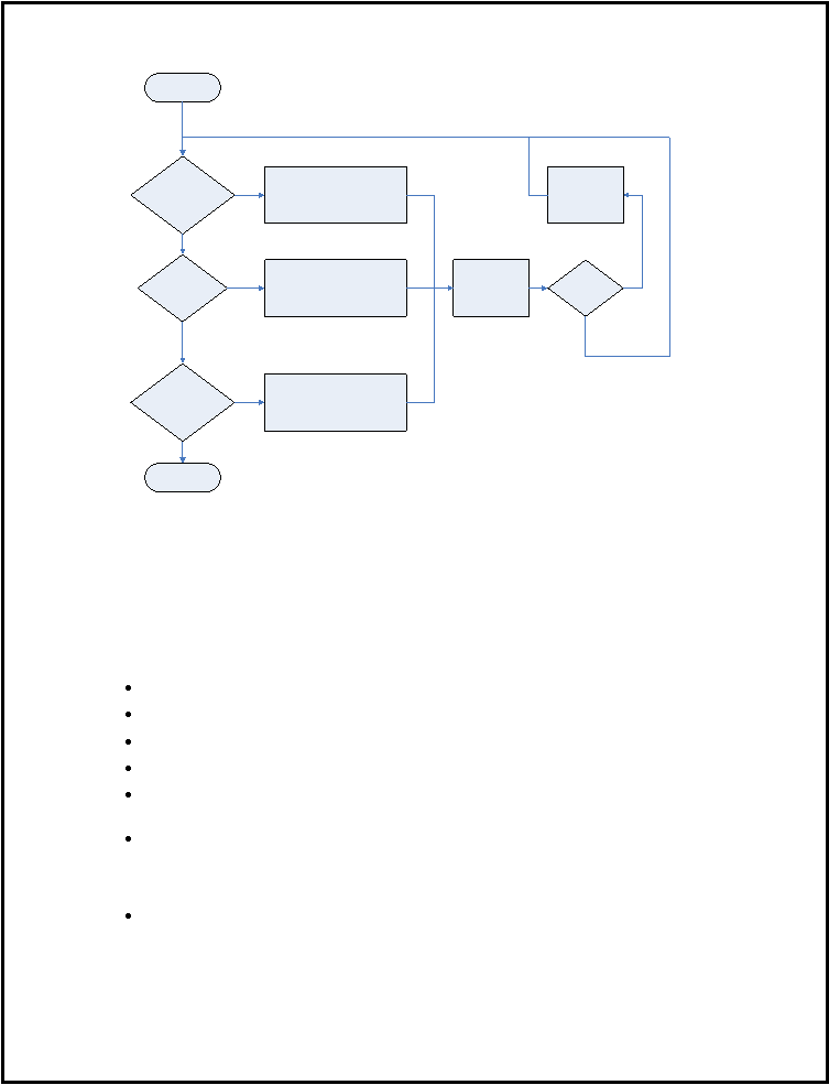 SAE J2735-Draft-Rev29 [issued: 12-11-08]
-
268 -
This is an SAE Motor Vehicle Council draft document of the DSRC committee, subject to change.
Start
snapshotctr
=
0
Number of Event
snapshots In Buffer
>
0
Number of Start
/
Stop snapshots in
Buffer
>
0
Number of Periodic
snapshots in Buffer
>
0
Add oldest Event snapshot to
message
Clear Buffer cell
Add oldest Start
\
Stop snapshot to
message
Clear Buffer cell
Add oldest Periodic snapshot to
message
Clear Buffer cell
End
Y
Y
Y
snapshotctr
=
snapshotctr
+
1
snapshotctr
=
4
Transmit message
Snapshotctr
=
0
Definition of variable
snapshotctr
=
counter of snapshots in each message
;
counts up to four for each
message
Note
:
Start
/
Stop and periodic snapshots may only be transmitted in a message with
the same PSN
–
a different PSN requires a new message
.
N
Y
N
N
N
Figure 13 Transmit Loop
Probe Segment Number (PSN)
The periodic snapshots are tagged with a short-lived Probe Segment Number (PSN). The PSN is regularly
changed to ensure privacy. This change occurs following either 120 seconds or 1 km whichever comes
last. To aid anonymity:
Snapshots within the same probe message shall not contain different PSNs.
The same PSN cannot be transmitted from the same vehicle to more than one RSU.
PSNs are limited in duration to 120 seconds or 1 km whichever comes last.
Separate messages can be transmitted to a single RSU with different PSNs.
When a new PSN is generated there is a random changeover gap of 50 to 250 m or 3 to 13 seconds
whichever comes first. Two random numbers should be used, one for distance one for time.
When the vehicle identifies a "Leave RSU" state, all remaining snapshots containing a PSN that
has already been sent to an RSU will be purged from the buffer. (A "Leave RSU" event/state is
when the RSU communications link is not available for 6 minutes or 4 km, which ever comes
first.)
Event snapshots do not contain a PSN.
The figure on the next page illustrates the reasons for changing a PSN.
|
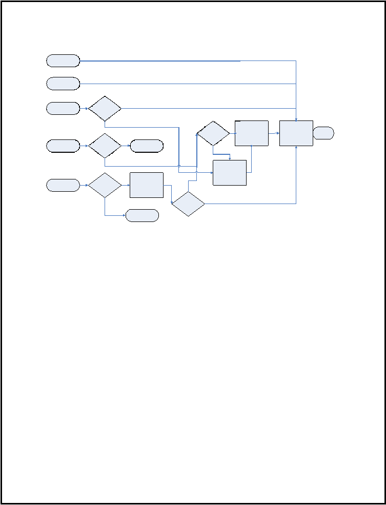 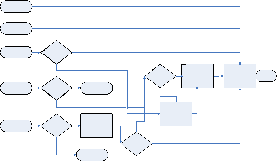 SAE J2735-Draft-Rev29 [issued: 12-11-08]
-
269 -
This is an SAE Motor Vehicle Council draft document of the DSRC committee, subject to change.
Initialization
(
OBE
turn
-
on
)
Current PSN
expires
(
time and
distance
)
All Snapshots
Transmitted
Lose RSE
Connectivity
New PMM
Request
Dump all
messages with
previously
transmitted PSNs
Under PMM
?
Under PMM
?
Generate GAP
Generate New
PSN
End
End
(
Do Nothing
)
Is Buffer Empty
End
(
Do Nothing
)
Y
Y
N
N
Y
N
Under Existing
GAP
Y
N
Wait for Gap to
elapse
Under PMM
?
N
Y
Figure 14 PSN Change Reasons
Buffer Overflow - Snapshot Deletion
The OBU should store a minimum of 30 Probe Data Snapshots to ensure data relevancy for areas of
sparsely deployed RSU. When the snapshot buffer is full the snapshots should be deleted in the in the
following order: first periodic, then start/stop and last events. The deletion of the periodic snapshots
should follow the following process:
The oldest periodic snapshot is deleted last. The first snapshot to be deleted is second oldest, then the
fourth, sixth etcetera. This is repeated until the snapshot in the position halfway between the oldest and the
newest period snapshot is met and then the process is repeated starting again at the snapshot in the second
position. This provides two features: the oldest periodic snapshot is kept to assist in the estimate of travel
time and the deletion of snapshots is preferentially applied to the older data that is less relevant. The
process is illustrated in the figure below. The figure does not illustrate the effect of the deletion process if
there are event snapshots; the effect of these is to reduce the point at which the deletion cycle is repeated.
|
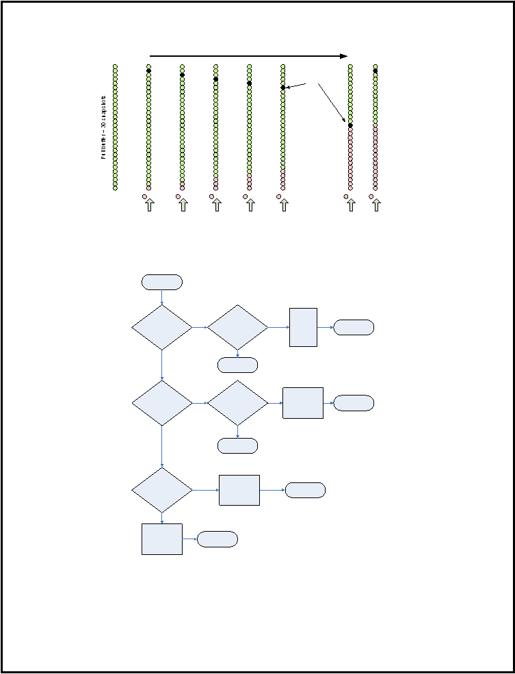 SAE J2735-Draft-Rev29 [issued: 12-11-08]
-
270 -
This is an SAE Motor Vehicle Council draft document of the DSRC committee, subject to change.
… etc
...
New
snapshots
time
#
1
#
2
#
3
#
4
#
5
#
14
#
15
… etc
...
Deleted
snapshots
Figure 15 Snapshot Deletion Process
The figure below illustrates the one implementation of the snapshot writing process.
Buffer Full with Event
snapshots
?
Buffer Full of Events
and Start
/
Stop
snapshots
?
Buffer Full
?
Start
(
New
snapshot to be
added to buffer
)
Record snapshot
New snapshot is Event
?
End
(
Do Not
record snapshot
)
Delete
oldest event
snapshot
.
Record new
event
snapshot
.
End
New snapshot is Event
or Start
/
Stop snapshot
?
Delete oldest start
/
stop snapshot
.
Record new start
/
stop snapshot
End
(
Do Not
record snapshot
)
End
End
Delete according
to periodic
snapshot deletion
scheme
–
see text
End
Y
Y
Y
Y
N
N
Y
N
N
N
Figure 16 Snapshot Writing Procedure
|
 SAE J2735-Draft-Rev29 [issued: 12-11-08]
-
271 -
This is an SAE Motor Vehicle Council draft document of the DSRC committee, subject to change.
Probe Data Message Sets Received By an RSU
When an RSU receives a Probe Data Message Set it will send the data to the RSU’s primary Network
Access Point (NAP). The NAP then forwards the data to the Service Delivery Node (SDN) which
maintains Subscriber Registration and Subscription information and publishes the data to all valid
subscribers such as a local Traffic Operation Center or third party Content Service Providers.
Local systems, if authorized, can subscribe to probe data directly from the RSU. This will allow local
systems and signal controllers to use probe data directly and significantly reduce bandwidth requirements.
Vehicle Anonymity
Probe snapshots when sent to the RSU and forwarded to an SDN publish/subscribe service normally will
contain no record
15
of the originating vehicle nor will there be any information that directly links one
snapshot with another snapshot. To aid anonymity:
The collection of snapshots does not begin until 500m after the vehicle start up. All snapshots are
purged from vehicle memory as they are sent to an RSU and when vehicle is turned off.
Probe Data Security
Probe Data Message Sets are sent, unicast, to the RSU. The RSU will NOT send an acknowledgement
back to the OBU; therefore, if the message does not get through it’s lost. All Probe Messages will be
authenticated to ensure message validity and protect their contents. Key management is assumed to be
handled by another layer, such as the IEEE 1609.2 Security Layer
Probe Data Message Management
This message is broadcast from the RSU to all vehicles. Its purpose is to change the snapshot generation
characteristics of the OBU. For example, the OBU can be instructed to take snapshots more frequently and
transmit them more often. It does not change the snapshot message.
Probe management is temporary. By default a probe message management process ceases when a new
RSU that supports probe messages is contacted. This case overrides the termination settings below.
Probe messages can be set to terminate as follows:
A time-based duration expires
A distance-based length has been traversed, or
A vehicle is out-of-range of the current RSU
When a probe management message terminates the default conditions again operate in the OBU unless or
until a new probe management message is received. Probe management messages can perform the
following functions either singly or in combination:
Control the production of snapshots by either distance or time
Direct the management message to vehicles moving in specified directions
Control how often snapshots are transmitted
Be applied to only a random sample of vehicles
Modify the thresholds of when event snapshots are triggered
Modify the thresholds of start/stop snapshots
15
Some pubic fleet vehicle types may provide additional identity information.
|
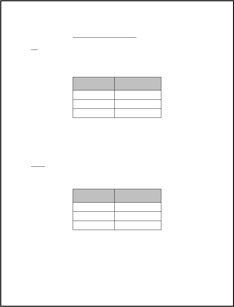 SAE J2735-Draft-Rev29 [issued: 12-11-08]
-
272 -
This is an SAE Motor Vehicle Council draft document of the DSRC committee, subject to change.
Probe Message Management: Time or Distance Periodic Snapshot Generation
The first component of the Time or Distance Snapshot Generation element is a switch indicating if
snapshot generation will be based on a time interval or distance interval.
If time is to be used the message will have the capability of changing the default snapshot intervals as well
as the speeds for these intervals:
T1
= 4 seconds at S1 = 20mph
T2
= 20 seconds at S2
= 60mph
Speed
Time Between
Snapshots
= S¹
T¹
>S
1
& < S²
linear extrapolation
>S
2
T²
Table X Table - Title Needed as per SAE style rules
This will allow applications and users to fine tune the probe data being received. For example, if this is an
urban freeway where the speeds are high but the RSUs are close together then the 20 seconds at 60mph
may be changed to 10 seconds to provide a finer geographic resolution of the data.
Additionally, an alternative method would be to enter a single time interval for T1
and T2
, thus taking
snapshots at constant intervals, independent of speed, such as one per second (T1 = 1 and T2
= 1).
If distance is to be used then a similar set of parameters can be sent, but instead the times (T
1
and T2) would
be replaced with distances (D1
and D2
) in meters. In the same manner as the time calculation above the
distance used between speeds S1 and S2 will be linearly extrapolated. As before, two speeds (S1
and S2
) can
also be set, yielding the following:
Speed
Distance Between
Snapshots
= S¹
D¹
>S
1
& < S²
linear extrapolation
>S
2
D²
Table X Table - Title Needed as per SAE style rules
This allows the operator to change the profile of the data collection policy to meet circumstances such as
incidents. For example, an incident typically causes the traffic upstream of the incident to slow, but the
downstream traffic flows fast. In this case D1
can be made small to accommodate queue measurement and
D2 made large to space out the snapshots downstream of the incident.
An allowed alternative method would be to enter a single distance interval for D1
and D2
, thus taking
snapshots at constant distance intervals, independent of speed, such as once per 10 meters (D1
= 10 and D2
|
 SAE J2735-Draft-Rev29 [issued: 12-11-08]
-
273 -
This is an SAE Motor Vehicle Council draft document of the DSRC committee, subject to change.
= 10). This would allow the user managing the probe data generation, given knowledge of the distance and
direction to the next RSU, to evenly geographically space snapshots.
Probe Message Management: Interval between Probe Message Broadcasts
This parameter will control when the snapshots are transmitted back to the RSU as part of probe messages.
This will allow the management message to request that probe messages be sent to the RSU at an interval
other than the default (which is when a vehicle first enters range of an RSU). For example, this might
allow an adaptive control system to request periodic snapshots be generated every two seconds and probe
messages transmitted every four seconds (i.e., each probe message would contain only 2 periodic
snapshots) while in range of the RSU.
DCK Text: A longer duration example might be helpful here as well. For example, an RSU with a radius
range of 1000m along a road way (and therefore spanning 2000M of any vehicles path) would have an
individual OBU in view for about 400 seconds if the vehicle was traveling at ~10mph. This is about as
long as possible to achieve. What management example could we provide for this use case?
Probe Message Management: Termination
This parameter is required to ensure that the OBU snapshot generation settings revert back from managed
settings to the default settings. This parameter will contain data such that when the first of the follow
16
occurs, probe snapshot generation returns to the default settings:
A time-based duration expires
A distance-based duration expires (i.e., a vehicle travels a certain distance)
A vehicle is out-of-range of the current RSU for a threshold time (default 5 seconds) – i.e. after 5
seconds of no RSU signal is received then management process is terminated
These values can be set independently, for example if time and out of range are not set then distance only
applies. For example if distance were set at 1km for westbound vehicles then is no new RSUs were
encountered and no events or stops and starts occurred the OBU would collect one snapshot per kilometer
for the next 30 km.
Probe Message Management: Vehicle Status Element Triggers
This parameter is used to adjust event triggered snapshot generation by adjusting the threshold of or
transitions in various vehicle status elements which can be used as triggers.
For example, this parameter might include the vehicle status element for vertical acceleration, and a
reduced threshold value. Thus, this would generate more snapshots that could be used as a roughness
measurement. Another example would be to reduce the threshold of vertical g forces on each wheel to zero
to calibrate road slope as a function of speed to determine adverse cambers.
Probe Message Management: Vehicle Sampling
The probe management message is a broadcast message. Therefore, all vehicles within range of an RSU
receive this message and respond to it. However, it is possible to control the percentage sample of vehicles
which will respond to any message by including in the probe management message a vehicle sampling
parameter. This parameter has two digits (range 0 to 255), which represent the range of the last digit of the
OBUs MAC address for those vehicles to which the management message applies.
16
This text (...when the first of the follow ...) makes no sense to me, re-word?
|
 SAE J2735-Draft-Rev29 [issued: 12-11-08]
-
274 -
This is an SAE Motor Vehicle Council draft document of the DSRC committee, subject to change.
For example, by setting the first value to 0 and the second value to 63, all those OBUs which that have a
current MAC address that ends in the range 0 to 63 would use this probe management message, thereby
yielding a sample of one fourth of all vehicles (MAC address are hexadecimal, much like an IP address,
and the last digit can vary from 0 to 255 and over large populations are distributed randomly ). A vehicle
OBU with a MAC address ending in 64 or higher would not respond to this probe management message.
A statistically similar result could be achieved by using the values 64 and 127, also resulting in 1/4
th
of the
local OBU population being affected. As a best practice, the issuer of the message should randomly vary
the start and stop values selected to ensure that the burden of supporting the probe management message is
evenly distributed among the entire OBU populations.
Probe Message Management: Managed Vehicle Heading
The probe management message will also include a parameter to indicate which direction-of-travel
17
it
applies to. The Managed Vehicle Heading parameter includes a heading value range, limiting its
application to only vehicles which are currently traveling in that direction. Heading is described by
dividing a range of 360 degrees into 16 different segments (each of which are 22.5° wide) and can be
combined to define the required heading of the affected vehicles when entering the region.
For example, by setting the value to 0xFFFF all possible headings are selected and therefore any vehicle
receiving the probe management message will be affected. If a value of 0x0081 was used only those
vehicles traveling directly east-bound would be affected, while a value of 0x8100 would indicate only
west-bound vehicles, and 0x8181 would include both directions.
Probe Message Management: Start and Stop Threshold Settings
The management message allows the start and stop thresholds to be modified. The default stop time
threshold is 5 seconds and the default last stop threshold time is 15 seconds. The default start speed
threshold is 10 mph. These three values can be modified at by the local RSU. The default values may be
inappropriate for the case of ramp metering where the start stop thresholds are greater than than the vehicle
metering rate.
The figure below illustrates one implementation of the probe management process.
17
Note: We are now using the same direction of travel “slice of the compass value” that the other
messages use, so I added the example text in the next paragraph, DCK.
|
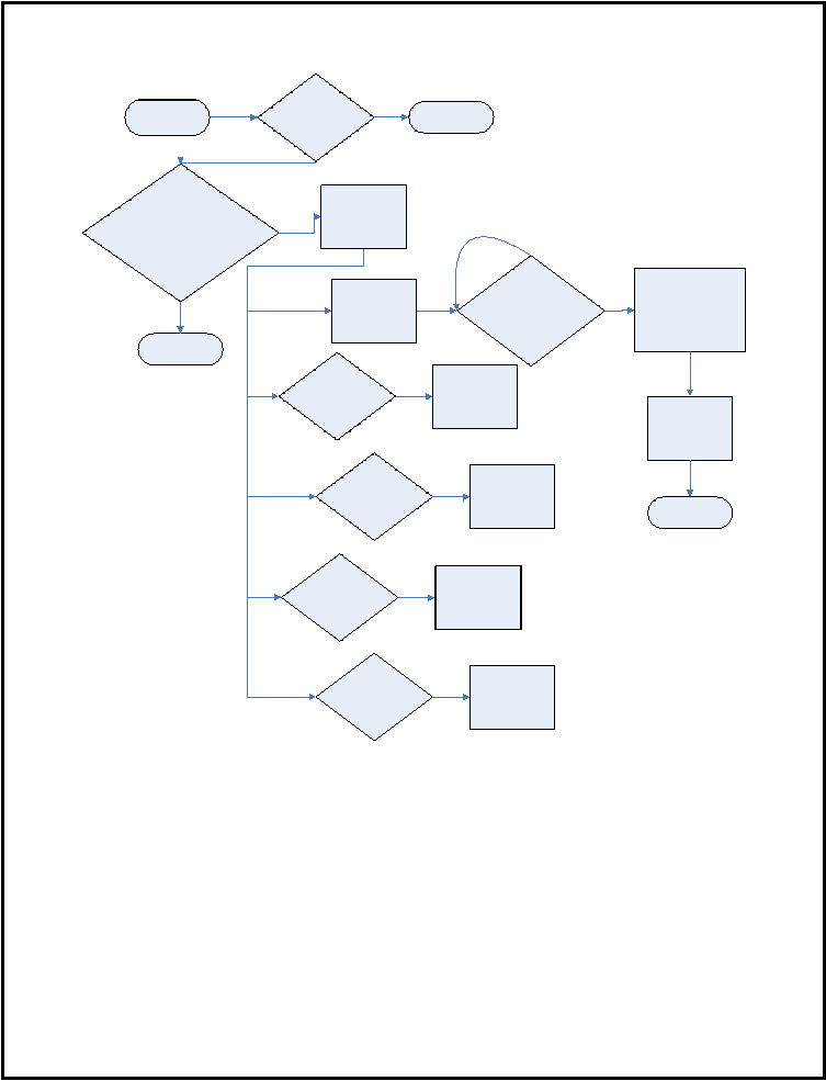 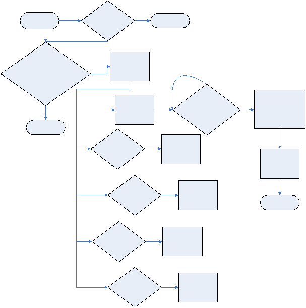 SAE J2735-Draft-Rev29 [issued: 12-11-08]
-
275 -
This is an SAE Motor Vehicle Council draft document of the DSRC committee, subject to change.
Figure 17 Probe Management Process (need to correct text in this figure)
Do the last
2
digits of the last
\
current PSN match the Sample
element AND does current
Heading match the Directions
element
?
End
(
Do Nothing
)
Y
N
Has Termination Time
OR Distance been
reached OR has a new
RSE been encountered
Should Snapshot
Collection Method
be modified
Y
Y
Should Start
\
Stop
Thresholds be
modified
Y
Should
Transmission
Interval be modified
Y
Should Event
Thresholds be
modified
Y
N
Set New
Collection Policy
based on Time or
Distance
Set New Start\
Stop Thresholds
Set New
Transmission
Interval
Set New Event
Thresholds
Set Termination
Policy based
onTime or
Distance
Set Collection Method
,
Start
\
Stop Thresholds
,
Transmission Interval
,
and Event Thresholds
to Default
End
Receive a Probe
Management
Message
Is this msg in use
N
Y
End
(
Do Nothing
)
Generate New
PSN w
/
o Gap
Generate New
PSN with Gap
|
 SAE J2735-Draft-Rev29 [issued: 12-11-08]
-
276 -
This is an SAE Motor Vehicle Council draft document of the DSRC committee, subject to change.
Annex F Emergency Vehicle Message Use and Operation
1. Application Description
This is a vehicle to infrastructure message, it is typically sent from an emergency vehicle or transit vehicle.
The Emergency Vehicle Message set consists of three distinct messages, as outlined below. Each will be
discussed in turn in this annex.
Signal Request Message (SRM)
Used to request a preemption or
priority signal state from a signalized
intersection.
Signal Status Message(SSM)
Used to relate the current preemption or
priority signal state(s) a signalized
intersection may be in.
Emergency Vehicle Approaching Message
Used to announce to other vehicles that such
an emergency vehicle is operating in the
local area.
The first two of these messages are used in relation to the control of a signalized intersection during
emergency response operations. The first is transmitted by an emergency vehicle and is used by the
controller of a signalized intersection. The second is output by the local RSU (and originally created by the
signal controller) if a preemption or priority request is granted, causing a change to the signal state status
data of the SPAT message stream being sent, and allows emergency vehicles and priority transit to learn
aspects of the internal state of the controller. The third message is emitted by public safety vehicles while
responding to emergencies, so as to alert other nearby vehicles to that fact.
Restating the signal operations in greater detail: The first message, the Signal Request Message (SRM) is
transmitted by the requesting vehicle (a PSOBU equipped vehicle) to the RSU for that intersection (and
then on to the ASC device). This message is sent after the vehicle has received and processed the “zones”
present in the intersection map message which relates a specific preemption or priority id to a geographical
area. The advanced signal controller (ASC), which is continuously emitting SPAT style messages to relate
the current signal state to other vehicles in the area, will also issue a Signal Status Message (SSM) if there
is one or more active or pending preemption or priority events to report. Note that this message is
transmitted by the local intersection RSU in a broadcast style. There is a potential that multiple local
vehicles will be simultaneously sending Signal Request Messages as they approach the intersection and
receive the RSU/ASC generated Signal Status Message in this time interval. The required logic to decode
the “winner” in such a conflict is outside the scope of this of document and resides in the ASC. The
outcome of that process is reflected in the Signal Status Message. These two messages (along with the
SPAT and MAP message discussed elsewhere) are also considered part of the intersection control message
set.
The third message, or Emergency Vehicle Approaching Message, (EVA) is a simple broadcast message to
alert nearby vehicles of the presence of an emergency vehicle operating in the area. It uses the familiar
ITIS codes for this message, packaged in the format defined in the Roadside Alert message, but adds
additional useful details about the emergency vehicle itself (its use of sirens, lights and other alerts, its basic
type or class of vehicle). The purpose of this message is to provide warning to other drivers when a
PSOBU equipped vehicle such as police, fire or ambulance is in the vicinity and a potential interference
with the emergency vehicle's path is eminent.
Two safety issues are being addressed by the 3rd
message. First, the notification to the driver that an
emergency vehicle with its siren/lights flashing is in the area. This can occur even if the emergency lights
are hidden behind an obstruction and the sirens cannot be heard above the surrounding audio (noise, radio,
|
 SAE J2735-Draft-Rev29 [issued: 12-11-08]
-
277 -
This is an SAE Motor Vehicle Council draft document of the DSRC committee, subject to change.
etc). The second is identification of where the vehicle is and what to do to avoid interference with its path.
It should also be noted that many times police will respond to a service call with lights flashing but without
sirens being active (an event which is also covered
18
).
When an emergency vehicle and other surrounding vehicles are equipped with PSOBU’s and OBU's, the
vehicles can establish communication when they are within range of each other and share information
relative to their location and direction. A PSOBU is required in emergency vehicles as this is a special
application that is not available to standard OBU's. This application should be implemented as a high
powered application to extend range. It is expected that the surrounding OBUs will receive this message
from the PSOBU well before they begin to receive the normal BSM transmission from the same vehicle.
From calculations resulting from this information, the private vehicle can first notify its driver of the
situation then may offer suggestions to avoid path interference. While difficult to make this function
robust and precise, enough information can be made available to the driver that improvements over a non-
equipped system can be significant.
2. Preconditions for operation:
The following general conditions are presumed to prevail in this application:
1.
The private vehicles are equipped with active OBU.
2.
The emergency vehicles are equipped with active PSOBU
and can issue SRM and EVA messages.
3.
The emergency vehicles has previously received a MAP message for the target intersection which
contains “zone” data
[RS42]to relate specific priority or preemption values to specific service zones
in the intersection.
4.
The intersection is equipped with an RSU and ASC
[RS43].
5.
The intersection [RS44] equipment can handle the intersection control messages
(SPAT, MAP, SRM, SSM).
6.
All systems are active and functional.[RS45]
7.
Emergency vehicles can provide location, speed, and direction of travel. This is required for the
EVA message and optional for the SRM message. The messages can be used when the direction
of travel is unknown (often the case when a vehicle is pulling out into traffic). ITIS codes and
speed./heading denote when a vehicle is stopped (indicating at scene).
8.
Private vehicles have available thier location, speed, direction of travel.
3. Flow of Events
The first two messages are handled in the initial use case to control the intersection. The 3rd
messages is
then handled in another use case. In actual practice, the flow of events of these two use cases would be
interspersed in time.
Flow of events, Typical Intersection use
18
Alerting others to the presence of the siren or flashing lights is optional and the standard allows for
“silent running” response as well. Police officials differ in opinion on the utility of this aspect of the
message, so its use is optional.
|
 SAE J2735-Draft-Rev29 [issued: 12-11-08]
-
278 -
This is an SAE Motor Vehicle Council draft document of the DSRC committee, subject to change.
1.
Vehicle “A”, a PSOBU equipped vehicle is operating in a non-emergency condition. It is acting
similarly to any OBU equipped vehicle and it sends typical vehicle Basic Safety Messages (BSM). It
also receives MAP and SPAT messages about the local signalized intersections, from which it can
extract the preemption or priority zones data when needed. The MAP and PSAT message are being
sent out by the RSU for the target intersection on a periodic basis.
2.
Vehicle "A" determines that activation of an Signal Request message is needed. This could occur
through various determinants, but is likely to be combined with the next use case at the same time.
3.
This activates a PSOBU broadcast of Signal Request message (SRM), which contains the preemption
or priory requested as well as the optional “BSM blob” with current location information, speed, and
direction of travel in it. See GG note about need for destination here, unresolved issue. Current codes
support “at destination” but not where it is.
4.
The intersection RSU, receives the of Signal Request message (SRM) and hands it to the ASC for
further processing. The ASC looks that the data, its own current state, and any required validity
credentials and makes a determination regarding how to respond to the request.
5.
The ASC sends to the RSU (for broadcast) the Signal Status message (SSM) which contains a
summary of the new state of the control with respect to preemptions and priority requests. The
updated SPAT message (which may now reflect a transition to a preemption or priority condition) is
also sent from the ASC to the RSU. The RSU broadcasts these in the normal way.
6.
Vehicle "A" receiving the SSM and can determine if and when the request will become the current
state of the signal. It also will be receiving the SPAT message where this can be further confirmed.
7.
This process repeats (steps 4 to 7) until the vehicle has past the intersection and the intersection is then
released to either resume normal operations or to process the next ranking preemption or priority
request that it has received. A timeout event will occur in the ASC if the requesting SRM is missing
for more than 3 seconds.
8.
Vehicle "A" determines that it has past the intersection, and sends a new Signal Request message
(SRM) with the cancel bit set in the signal request type field for a period of time.
9.
The intersection RSU, receives the of Signal Request message (SRM) with the cancel bit set and hands
it to the ASC for further processing. The ASC looks that the data, its own current state, and any
required validity credentials and makes a determination regarding how to respond to the request. It
may allow another pending request to become the active one (in which case we again cycle over steps
4 to 7) or it may resume normal operations (returning to step one).
10.
Vehicle "A" may note that the received SSM has removed its request from those active and pending,
and therefore ceases sending the Signal Request message (SRM) with the cancel bit set, or after a
duration of 3 seconds may simply cease sending.
Flow of events, Typical EVA use
1.
Vehicle “A”, a PSOBU equipped vehicle is operating in a non-emergency condition. It is acting
similarly to any OBU equipped vehicle and it sends typical vehicle Basic Safety Message (BSM).
2.
Vehicle "A" determines that activation of an Emergency Vehicle Approaching Warning is needed.
This could occur through various determinants such as activation of its siren and emergency lights, or
other inputs to be determined by application developers.
|
 SAE J2735-Draft-Rev29 [issued: 12-11-08]
-
279 -
This is an SAE Motor Vehicle Council draft document of the DSRC committee, subject to change.
3.
This activates a PSOBU broadcast of emergency notification warning, current location information,
speed, and direction of travel as well a vehicle type
4.
Vehicle “B”, which may be a standard OBU equipped vehicle or another PSOBU equipped vehicle in
the vicinity, receives the emergency notification message and other data.
5.
Vehicle “B” determines whether Vehicle "A’s" message is relevant (calculates its relative position to
the emergency vehicle and determines if a potential interference may exist). If not, no action is taken;
the vehicles may be moving away from each other, on a different street, etc.
6.
If an imminent interference is detected, an alarm of some type is sent to the driver's HMI. It is assumed
that vehicles will have differing levels of HMI sophistication.
7.
Data updates continue; When the Vehicle "B" path is no longer a potential interference for the PSOBU
equipped vehicle, the warning will terminate.
Vehicle "A"Hardware Devices:
PSOBU
Positional Sensors
Human-Machine Interface
Vehicle
System
Occupant
Service
Provider
Road
Department
Vehicle "A" Actors:
(What
entities play an active role in use)
X
X
Vehicle "B" Hardware Devices:
OBU
Positional Sensors
Human-Machine Interface
Occupant
Vehicle
System
Driver
Passenger
Service
Provider
Road
Department
Vehicle "B" Actors:
(What
entities play an active role in use)
X
X
Support information:
CAMP-VSC Task 3 Report, 2003
4. System Architecture and Concept of Operation
A PSOBU vehicle is put into emergency service. Upon being put into emergency service, emergency
messages begin being sent to surrounding vehicles and signal request messages are emitted as the vehicle
travels. The Emergency Vehicle Approaching Warning message includes: Location, Direction, Speed,
Type of vehicle, Type of response, Siren in use, Light bar in use, and Multiple [RS46]vehicles responding
(optional). See GG note about need for destination here, unresolved issue The signal request message
contains the requested priority or preemption value to be requested of each ASC, and some vehicle
identification number (nominally a fleet number or VIN number). Any signal state messages recovered
(from ASCs that are processing to this or another request) will contain the current active request and data
regarding which vehicle asked for it, as well as a sequence of other pending requests from other vehicles.
Private vehicles in the area may use the Emergency Vehicle Approaching data to analyze if they may
encounter the responding vehicle. If this is possible, applicable information may be communicated to the
|
 SAE J2735-Draft-Rev29 [issued: 12-11-08]
-
280 -
This is an SAE Motor Vehicle Council draft document of the DSRC committee, subject to change.
operator. The warning can advise the driver to be prepared to take actions to stay out of the path of the
responding vehicle. The warning could include information about:
The type of emergency vehicle
The location or proximity of the emergency vehicle
Instructions on action that the driver may want to take
The warning presented to the driver may be different depending upon the proximity of the emergency
vehicle to their vehicle. The closer the emergency vehicle is, the more severe the warning. If pre
determined emergency route information is available from a public safety vehicle, the information may be
sent via other applications.
In general, private vehicles are expected to ignore signal request and signal status messages. When a
preemption or priority event does occur in an intersection, they are informed of this by way of the
SPAT[RS47] message.
Other emergency vehicles that are responding, receiving the Emergency Vehicle Approaching message,
may use the data to analyze if they may encounter the responding vehicle. The warning can advise the
driver to be prepared to take actions to stay out of the path of the responding vehicle. The warning includes
information about:
The type of emergency vehicle
The location or proximity of the emergency vehicle
Instructions on action that the driver may want to take
The warning presented to the drivers may vary depending upon the proximity of other emergency vehicle
to their vehicle and the use of sirens by one or more responding vehicles. The closer the emergency vehicle
is, the more severe the warning that will be communicated to the operator.
In general, other emergency vehicles may also be sending signal requests and receiving signal status
messages at the same time (often in ad hoc convoys proceeding through the same intersection). The signal
state message may list their own signal requests as pending when another vehicle (ideally one ahead of
them) has been granted the preemption or priority first. When a preemption or priority event is occurring in
an intersection, they are also informed of this by way of the SPAT message, like private vehicles.
5. Application use with DSRC
The messages in this application are typically transmitted using the BER-DER encoding and the Wave
Short Message protocol (WSM) stack in a periodic broadcast mode on a high power channel (CCH or
SCH) to other devices (typically other mobile OBUs) who have determined to receive this type of message
(based on PSID value and running a suitable application). Upon reception of such messages they are
examined for message content and relevance regardless of any PSC provided by the sender.
If the message content is considered to be of a “low priority”
19
(such as standing static reports, permanent
school zones, and other semi permanent data such as construction warnings) then the message may be
transmitted using an XML encoding as an IP datagram over a service channel in a periodic broadcast mode
to other devices (typically other mobile OBUs) who have determined to receive this type of message (based
on PSID value and running a suitable application). Upon reception of such messages they are examined for
message content and relevance.
19
The ultimate determination of this classification, and therefore the encoding and bandwidth
allocated to either type of message is a local jurisdictional consideration.
|
 SAE J2735-Draft-Rev29 [issued: 12-11-08]
-
281 -
This is an SAE Motor Vehicle Council draft document of the DSRC committee, subject to change.
Therefore, this is a provider application that does not employ a Wave Basic Service Set (WBSS) as per
IEEE 1609.4 Clause 5.3 and there is no confirm and join operations. Receivers of these messages are
expected to process all such message regardless of the PSC found (typically each device running a provider
application will have its own PSC to further classify its transmissions).
This application shall transmit its messages using an PSID value of “
19
” [the “emergency-warning”
service] as defined by IEEE 1609.4 or its successors. Multiple applications, each with their own PSC data,
are expected to be found operating in overlapping local coverage areas but using the same PSID and this
message set. Based on the data exchanged in this application, devices may determine the need to initiate
other services or applications using other PSID values. The message priority of this application shall be
set, as per Annex A of this document, to the value determined for devices sending this message. The
expected repetition rate for the messages broadcast in this application is nominally to be one new message
every half second for BER-DER WSM encodings. The expected repetition rate for the messages broadcast
in this application is nominally to be one new message every two seconds for XML encodings. These
values may vary based on other system allocation requirements.
|
 SAE J2735-Draft-Rev29 [issued: 12-11-08]
-
282 -
This is an SAE Motor Vehicle Council draft document of the DSRC committee, subject to change.
Annex G Roadside Alerting Message Use and Operation
1. Application Description
The purpose of the Roadside Alerting message is to provide warnings to a driver from either a RSU or a
PSOBU equipped vehicle such as police, fire, transportation, or ambulance vehicle which is sending data
about a nearby event of interest to travelers. This message was originally developed by the SAE ATIS
committee. It has been used by the DSRC committee in the initial published version of the standard (as an
external imported data concept), and with this edition has been brought into DSRC standard itself with
minor modifications to take advantage of the BER-DER encoding style now being used. The message
allows a sender to “strip down” the more verbose ATIS event message and send the critical content ITIS
phrase content over the DSRC WSM stack. Variations of the message, used when less urgent content is to
be sent, can be encoded over XML and sent as an IP datagram. Examples of the proper use and encoding
of this message are covered in the DSRC Users Guide documents.
2. Preconditions for operation:
The following general conditions are presumed to prevail in this application:
1
The private vehicles are equipped with active OBU.
2
There is an RSU or an incident response vehicle equipped with active PSOBU in range.
3
Both systems are active and functional.
4
Private vehicles have available it's location, speed, direction of travel (to filter content with)
3. Flow of Events
Flow of events
1
The sender (an RSU or an PSOBU) receives or creates a suitable Roadside Alert message for
transmission .
2
The sender (an RSU or an PSOBU) begins transmitting the message using the proper encoding,
channel and repetitive rate.
3
The Vehicle, which is typically a standard OBU equipped vehicle in the vicinity, receives the
message for the first time
4
The Vehicle determines whether the message is relevant (calculates its relative position to the
event and determines if a potential interference may exist). If not, no action is taken; the vehicle may be
moving away from the event, it may not apply, or it may have already been processed.
5
If an imminent interference is detected, an alarm of some type is sent to the driver's HMI. It is
assumed that vehicles will have differing levels of HMI sophistication.
6
Data updates continue as warranted and depending on the event type.
Sender Devices:
And RSU or an PSOBU
|
 SAE J2735-Draft-Rev29 [issued: 12-11-08]
-
283 -
This is an SAE Motor Vehicle Council draft document of the DSRC committee, subject to change.
Vehicle
System
Occupant
Service
Provider
Road Department
Vehicle Actors:
(What
entities play an active role in
use)
X
X
Support information:
4. System Architecture and Concept of Operation
An RSU (or a PSOBU vehicle) is put into emergency service by the reception or the creation of a Roadside
alert message. The messages begin being sent to surrounding vehicles (using the WSM for urgent
messages and IP for less urgent advisory type messages). The message content includes: Location,
Direction (applicability), and a set of descriptive ITIS codes.
Private vehicles in the area may use this data to analyze the event when they they receive the data. If this is
relevant, applicable information may be communicated to the operator. The warning could include
information about:
The type of event, a general event description.
The location or proximity of the event
Instructions on action that the driver may want to take
The warning presented to the driver may be different depending upon the type and its proximity to the
receiving vehicle If additional information is available from the sender, the information may be sent via
other applications and messages.
5. Application use with DSRC
The messages in this application are typically transmitted using the BER-DER encoding and the Wave The
messages in this application are typically transmitted using the BER-DER encoding and the Wave Short
Message protocol (WSM) stack in a periodic broadcast mode on a high power channel (CCH or SCH) to
other devices (typically other mobile OBUs) who have determined to receive this type of message (based
on PSID value and running a suitable application). Upon reception of such messages they are examined for
message content and relevance regardless of any PSC provided by the sender.
If the message content is considered to be of a “low priority”
20
(such as standing static reports, permanent
school zones, and other semi permanent data such as construction warnings) then the message may be
transmitted using an XML encoding as an IP datagram over a service channel in a periodic broadcast mode
to other devices (typically other mobile OBUs) who have determined to receive this type of message (based
on PSID value and running a suitable application). Upon reception of such messages they are examined for
message content and relevance.
Therefore, this is a provider application that does not employ a Wave Basic Service Set (WBSS) as per
IEEE 1609.4 Clause 5.3 and there is no confirm and join operations. Receivers of these messages are
expected to process all such message regardless of the PSC found (typically each device running a provider
application will have its own PSC to further classify its transmissions).
20
The ultimate determination of this classification, and therefore the encoding and bandwidth
allocated to either type of message is a local jurisdictional consideration.
|
 SAE J2735-Draft-Rev29 [issued: 12-11-08]
-
284 -
This is an SAE Motor Vehicle Council draft document of the DSRC committee, subject to change.
This application shall transmit its messages using an PSID value of “
19
” [the “emergency-warning”
service] as defined by IEEE 1609.4 or its successors. Multiple applications, each with their own PSC data,
are expected to be found operating in overlapping local coverage areas but using the same PSID and this
message set. Based on the data exchanged in this application, devices may determine the need to initiate
other services or applications using other PSID values. The message priority of this application shall be
set, as per Annex A of this document, to the value determined for devices sending this message. The
expected repetition rate for the messages broadcast in this application is nominally to be one new message
every half second for BER-DER WSM encodings. The expected repetition rate for the messages broadcast
in this application is nominally to be one new message every two seconds for XML encodings. These
values may vary based on other system allocation requirements.
|
 SAE J2735-Draft-Rev29 [issued: 12-11-08]
-
285 -
This is an SAE Motor Vehicle Council draft document of the DSRC committee, subject to change.
Annex H Map and SPAT Message Use and Operation
1.
Introduction
There are four messages currently defined to support intersection mapping needs and relating signal phase
and timing data to OBUs. These message support the intelligent intersection needs of the VII program. All
of these are the result of field experience involving several dozen intersections where similar prototype
messages have been operating. The data content used in those messages was similar, but used a proprietary
encoding, now replaced by the standard BER-DER encoding format specified here. These four messages
(listed below) are mature but supporting documentation on how they are to be used remains to be
developed. This annex serves as a short introduction to the intended general use of the messages.
The four subject messages are:
Signal Phase and Timing Message
(SPAT)
Relates the current intersection signal light phases
Map Data
(MAP)
Relates the Physical Geometry of the intersection
Signal Request Message
(SRM)
Requests preempt or priority services
Signal Status Messages
(SSM)
Relates the internal state of the signal controller
1.1
Intended Audience
This document is written primarily for application and system programmers who write compliant software;
system architects who drive the DSRC message creation, distribution and consumption processes; and
content designers and managers such as city managers and their staff.
1.2
Philosophy of SPAT and MAPs
In normal use the OBU units are expected to receive the MAP message before entering the intersection.
This map message conveys all the physical geometry for one or more intersections and well as the
regulatory information (allowed maneuvers) for the intersection and assigns specific lane numbers to both
drivable vehicle lanes and other features of each intersection. When in the range of the intersection, the
SPAT message is broadcast from an RSU with the current signal state at all times. OBU users can relate
the (dynamic) SPAT message information to specific lanes of travel in the (static) MAP message and
determine the phase state of the intersection and for how long that state will persist. Two additional
messages (SRM and SSM) are used to request and the determine priority and preemption events. These
two messages are typically used by public safety and public transport OBUs only.
At a high level, the MAP message contains all the static (unchanging) information relating to one or more
intersections in the intersections data frame. This information (consisting of both required and optional
informational content) is determined for the intersection and broadcast in such a way that a cache of local
intersections can be maintained by the OBU. Besides describing the lane geometry paths and the allowed
maneuvers for each lane, the intersection data frame can provide additional information regarding barriers,
pedestrian walkways, shared roadways and rail lines that may affect vehicle movement.
By contrast the SPAT message contains the state of the intersection and got how long this state will persist
for each approach and lane that is active. The SPAT and MAP share a common lane numbering
assignment between them to allow mapping.
2.
The overall framework of the SPAT
The Signal Phase and Timing message (SPAT) uses a simple framework to provide a basic summary of the
signal state at any given time (dynamic data). The many optional elements defined in this message allow
|
 SAE J2735-Draft-Rev29 [issued: 12-11-08]
-
286 -
This is an SAE Motor Vehicle Council draft document of the DSRC committee, subject to change.
for both simple and complex signalized intersections to be modeled without additional overhead in the
message unless that overhead is needed (say to relate pedestrian lanes states, or other events that may not
be present in every intersection). Consult the prior definitions for specific details, but here is a general
overview of the structures defined in the SPAT message.
The overall use of the SPAT message is to reflect the current state of all lanes in all approaches in single
intersection. Any preemption or priority then follows in a structure for the whole intersection. Lanes that
are at the same state (with the same end time) are combined. Thus the simplest SPAT message consists on
two such states, one for the then active lanes/approach, and another for all the other lanes that at that time
share the state being stopped (a red state). The stopped (red) lanes are optionally not sent at other times
(the presumption being that any lane not enumerated in the SPAT is in fact set red).
Here is a message fragment illustrating this:
SPAT Message
Msg id = 0x0c (indicates a SPAT message)
SPAT id = TBD
(indicates a unique value for this intersection)
States
State #1
Lane Set
(list of lanes this applies to)
1, 2
Movement State(signal state or pedestrian state)
SignalState = Green light
TimeToChange = 12.3 seconds
YellowSignalState =
State #2
Lane Set
(list of lanes this applies to)
3,4.5.6, etc...
Movement State(signal state or pedestrian state)
SignalState = Red light
TimeToChange = Indeterminate for this state
YellowSignalState =
Preempt = none present
The SPAT message consists of a sequence of MovementStates for each lane in the intersection.
21
The
SPAT status information is associated with the lanes found in the MAP message by the use of shared lane
numbering values. The overall framework consists of the regionally unique intersectionID (required), the
collation of current lane states, any signal-wide preemption data, and some optional content (such as the
human readable name of the intersection) as follows. Some additional information regarding the internal
preemption or priority request status of the signal controller itself can be obtained in the Signal Status
Messages (SSM) message.
Up to 255 unique states can be sent, although more commonly only active states are sent at any time (the
phase of the active lane-approach, and all other lanes which are in a red-phase). Considering the
MovementState data frame further we see that it includes a great deal of timing information:
21
In these messages all lanes are given a unique number regardless of what approach they may
belong to. Therefore, an “approach” in a traffic engineering sense of the word always consists of one or
more defined lanes in these messages. Lane numbering value assignment is arbitrary, but some
conventions or best practices are expected to apply.
|
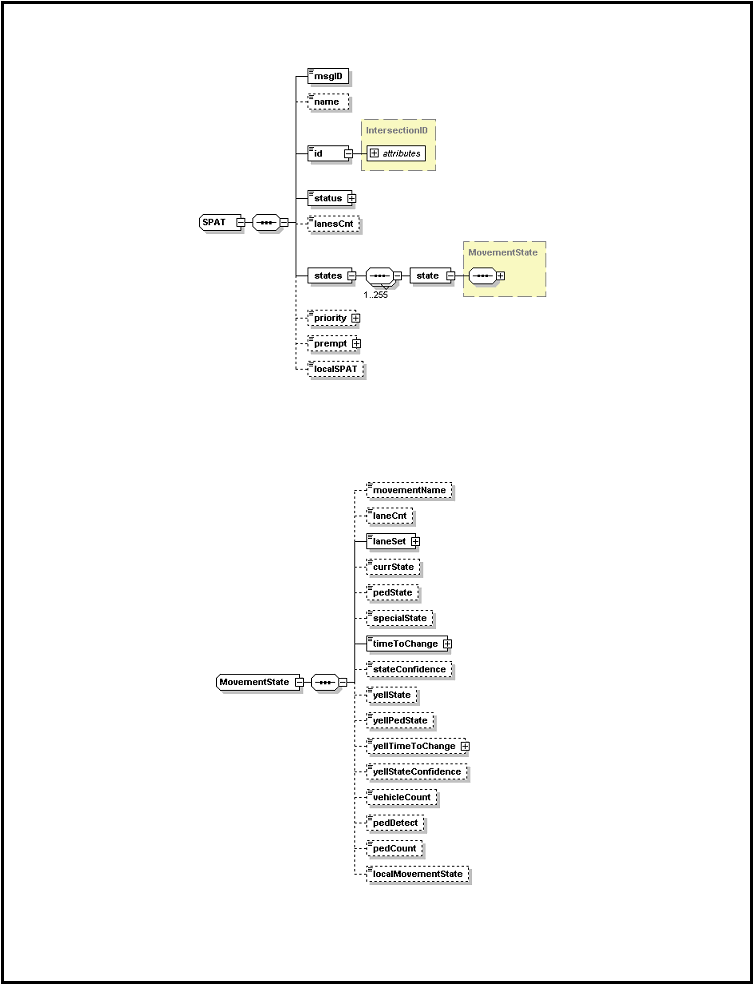 SAE J2735-Draft-Rev29 [issued: 12-11-08]
-
287 -
This is an SAE Motor Vehicle Council draft document of the DSRC committee, subject to change.
Note that only the laneSet (the list of lanes to which this applies) and the timeToChange are required, the
other elements are optional (indicated by the dotted lines). When presenting information about a vehicle
lane, the currState element is used. When presenting other types of timing data other elements are used.
For example, a pedestrian crosswalk timing uses the pedState element, while a train crossing an intersection
uses the specialState element.
|
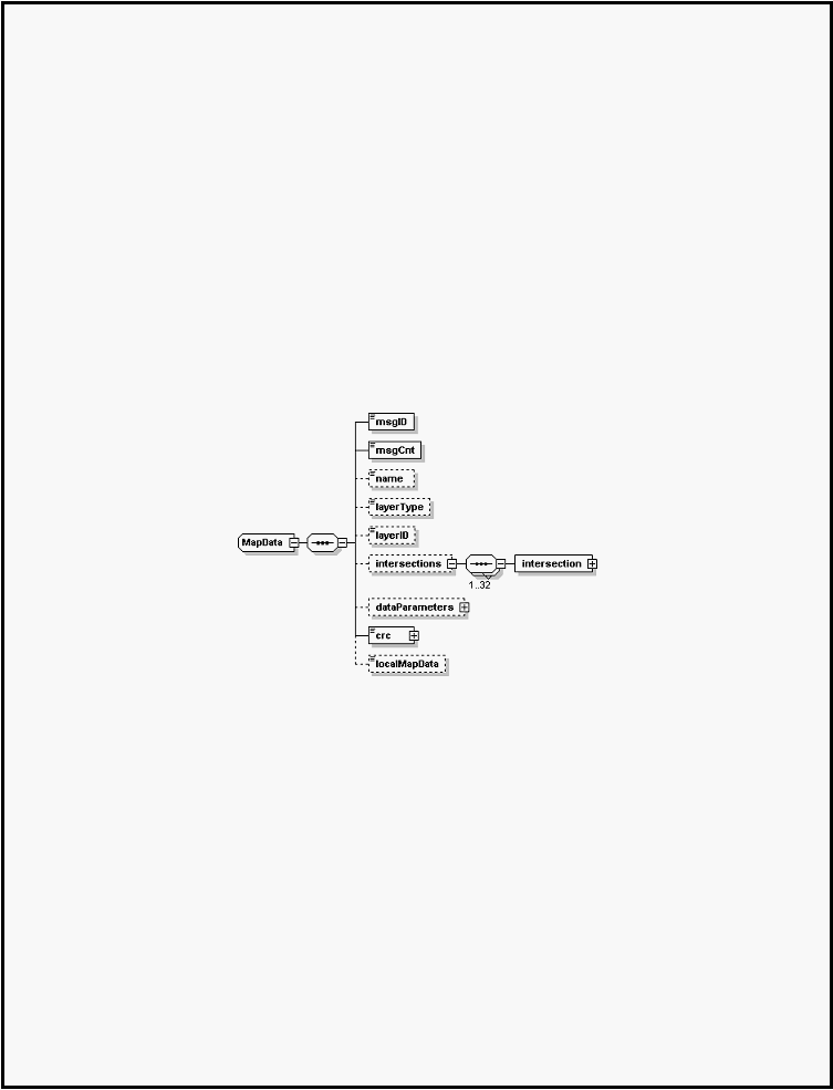 SAE J2735-Draft-Rev29 [issued: 12-11-08]
-
288 -
This is an SAE Motor Vehicle Council draft document of the DSRC committee, subject to change.
The lane set lists all the lanes (by their assigned number defined in the GID-MAP) that share this common
state and period. The currState element indicates the specific type of light (i.e. through arrow green,
yellow flashing etc.) present. The timeToChange indicates the minimum value of time for which this state
will persist in a count down timer. An optional confidence value may follow this and allows asserting
complex concepts like min or max times or times which are likely to change in adaptive intersections. A
second (optional) state called the “yellow state” allows sending phase time data about the NEXT phase of
the state and its duration. Its use will vary by local policies, but it is useful in relating yellow times as well
as pedestrian walkway clearance times. Various other optional data elements can also be sent including
the number of vehicles that have been detected or counted in the lane.
3.
The overall framework of the MAP
The MAP message is used to convey a number of different types of (static) maps in support of DSRC
messages. The intersection is but one kind of such data. Some of these remain to be defined in future
editions of the standard. However, the “intersections” or GID portion of the map is defined and is used
along with the SPAT message to relate information about intersections.
The intersection data frame, shown below, is used to relate all the needed physical geometry of an
intersection, assign the intersection a unique ID, and to assign numbers to specific lanes (the set of lanes
being a sub-set of an approach). Up to 32 intersections can be contained in a single map message.
Intersections are defined as collections of approaches, which are in turn defined as a collection of related
lanes. Each intersection has a regionally unique ID associated with this. It may optionally have a name
string as well. A reference point is used to define a precise position from which local offset values are used
to describe the geometry of the lanes. Other, optionally present reference points can be further defined in
the structures when needed to simplify extremely complex intersections. Intersections, like traffic lanes,
often follow repeating patterns, so a data compression scheme that allows “computed intersections” to
replicate simple intersections is provided (data elements refInterNum and orientation support this)
|
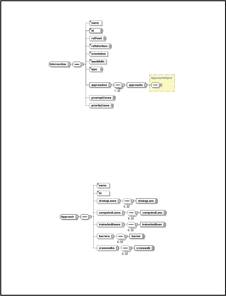 SAE J2735-Draft-Rev29 [issued: 12-11-08]
-
289 -
This is an SAE Motor Vehicle Council draft document of the DSRC committee, subject to change.
The ApproachObject structure allow arbitrary groupings of lanes to be created, as determined by the
designer. Lanes in this context refers to both driven vehicle use type lanes as well as several other lane
types defined by the standard. Lanes defined at this time include “pedestrian” lanes (cross walks) and
“special” lanes for shared lanes, rail track and other multi-modal uses, and “barriers” for various dividers.
Approach lanes are further divided into approach (ingress, incoming) and egress (outgoing) lanes, allowing
a clear division of the lanes coming into an intersection. Egress lanes are in fact optional and may
discarded under certain conditions when not needed
Within each approach are descriptions of one or more lanes of various types. Each of these can be related
in terms of its path and attributes (and in the SPAT its current status). A structure called nodeList is used
to relate the path of the lanes centerline with whatever degree of precision and number of data points are
required (including changes in width and elevation as needed).
|
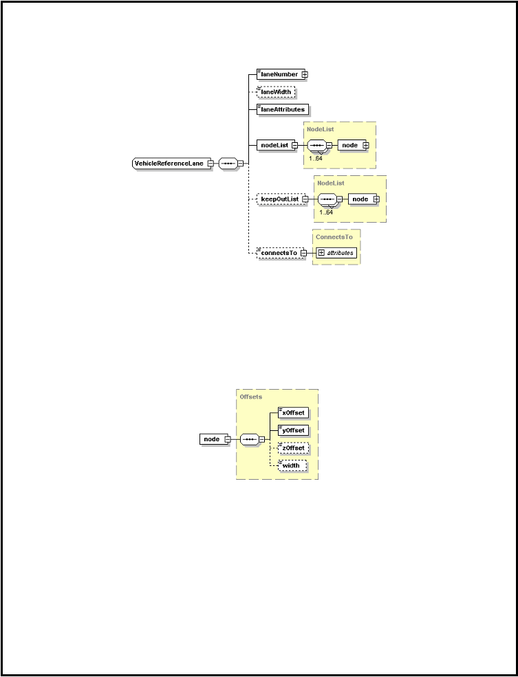 SAE J2735-Draft-Rev29 [issued: 12-11-08]
-
290 -
This is an SAE Motor Vehicle Council draft document of the DSRC committee, subject to change.
Here is the data structure of the driving lanes, used to relate the typical lane of traffic flow.
The laneAttributes is a bitstring which relates the allowed vehicle maneuvers such as noTurnOnRight etc.
In some complex cases (such as multiple soft left turns) the connectsTo data element can be present (in
ingress lanes) to further clarify how this lane interacts with the egress lanes.
The nodelist relates the path of the lane itself over the ground. The keepOutList is an optional further
overlay for places along the node list that the vehicle (or user) can not safely come to rest in (typical an area
marked do not stop or do not block on the ground). The nodelist itself it is made up of a sequence of from
one to 64 node points as shown below which relate the path in increments (precision) of 1.0 cm units. The
width or zOffset points, when present, establish a new standing value for that item until a subsequent
update, in a manner similar to the anchor points.
This collection of lane data is repeated for every lane to be described in the intersection. This consist of at
least all drivable lanes approaching the intersection and may include those lanes leaving the intersection
(egress lanes) and other supporting information (such as pedestrian lane details) as determined by the
message author.
In addition to the above, two optional structures (preemptionZones and priorityZones) are provided to
support priority and preemption requests at the intersection. These two items are used to determine which
specific request to make. They allow mapping of the intersection geometry into specific request zones and
values (0~7). They are identical in structure, using sets of the the SignalControlZone, shown below.
|
 SAE J2735-Draft-Rev29 [issued: 12-11-08]
-
291 -
This is an SAE Motor Vehicle Council draft document of the DSRC committee, subject to change.
Each request value (pValue) is associated here with a set of data (data) that outlines either the lanes it
covers (laneSet) or a set of zones (zones) made up of either encloses lanes (LaneSet) or a nodeList forming
a polygon of coverage. Public safety vehicles use this data to determine which request to make, then use
that value in the Signal Request Message (SRM) to request a preempt or priority from the intersection
controller. The changed state of the controller (if any) is reflected in both the SPAT message and the
Signal Status Message (SSM) message.
4. Additional details of message use
The use of this message set to correctly describe intersections and then model them with the SPAT will
involve a considerable number of additional details. At the time the current standard went to ballot, this
detail had not been created, but is expected to be placed into a subsequent users guide document along with
working examples.
|
 SAE J2735-Draft-Rev29 [issued: 12-11-08]
-
292 -
This is an SAE Motor Vehicle Council draft document of the DSRC committee, subject to change.
Annex I Cooperative Cruse Control (CCC) Use and Operation
1. Introduction
The Cooperative Cruise Control Message Set provides a mechanism for vehicles to effectively
communicate relevant information to each other, and operate as a coherent group. Vehicles will
communicate internally within the team in order to maintain group cohesion, operational safety, and
maximize individual and team mobility. The vehicle team will be able to communicate as a collective with
other vehicle teams, individual vehicles, and roadside infrastructure devices.
The goal in developing this message set is to standardize the process for communication within a
cooperative vehicle system, which is independent of the level of functional autonomy of the vehicle. The
message set is not meant to replace existing sensors and equipment on vehicles; rather, to enhance existing
sensor systems with information not directly acquired through intrinsic capabilities, enabling the formation
of a cooperative vehicle system.
In essence, the message set enables an adaptive cruise control capability, which utilizes low latency
communications in conjunction with vehicle sensors and controls. Data formatting follows the SAE J2735
message set. By utilizing this message set, the vehicle following distance can be dynamically managed in
cooperation with a driver. While it is not envisioned that full control of the vehicle is managed, the throttle
and brake may be may be utilized similar to current cruise control implementations, as well as audible and
visual warnings to the driver. A mechanism for providing active and automatic brake control may be
required for controlling the shorter following distances envisioned during cooperative cruise control
operations. Alterations to the preset driving condition will alert the driver while automatically ensuring a
safe following distance.
This message set is not meant to define such a system and set limits such as safe following distance, as
these are beyond the scope of the cooperative cruise control message set. System-related design concepts
should be considered in the development of the message set, where operational requirements and
implementation are left to vehicle OEMs, and the driver.
2. Operational Concept
The following section provides a definition for the operational concept of teaming operations, and more
specifically cruise control operations enhanced with low latent communications.
Team:
o
Finite number of vehicles.
o
Possessing DSRC communications.
o
Traveling in same direction.
o
Consecutively traveling in the same lane.
o
Vehicles shall be of compatible Vehicle Type as defined by the FHWA Office of Highway
Policy Information. The J2735 Vehicle Type data representation will be used.
o
Any single vehicle shall not be a member of more than one team concurrently.
Cooperative Cruise Control
o
Adaptive cruise control mechanism or operation.
o
Enhanced via low latent vehicle-to-vehicle and vehicle-to-infrastructure communications.
|
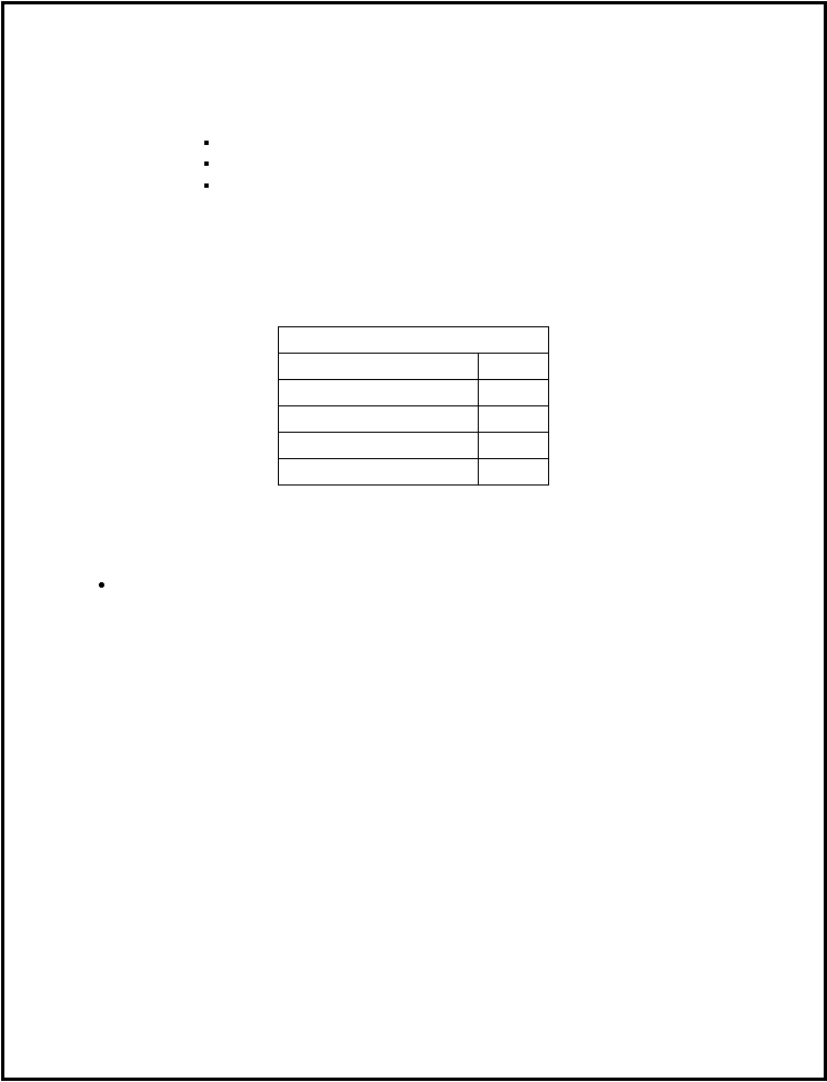 SAE J2735-Draft-Rev29 [issued: 12-11-08]
-
293 -
This is an SAE Motor Vehicle Council draft document of the DSRC committee, subject to change.
o
Vehicle shall have lane resolution positioning.
o
Voluntary yet implicit participation via traditional cruise control triggers.
o
Vehicle behaviors moderated via the guidelines of the team, including:
Target speed
Following distance thresholds
Destination (optional)
3. Cooperative Cruise Control Message Set
The Cooperative Cruise Control message set includes several messages which support the form, join, end,
leave, and status system operations. These are identified by message type identifiers. A table listing
message type identifiers follows.
Flag Type
Bit Flag
Form
0x0
Join
0x1
Leave
0x2
End
0x3
Team Status
0x4
Table 1: Message Type Identifiers
4. Form and Join Message Operations
Vehicle should broadcast a request to form, or it’s availability to join, a team.
o
Provides the ability to begin a team. Allows the vehicle to broadcast to the surrounding
environment that it is available and willing to initiate a team.
o
If multiple vehicles broadcast a request to form a team, the implementation will handle “Team
Leader” and “Team ID” designations relative to GPS location. (Team ID: 64 bit random
number)
|
 SAE J2735-Draft-Rev29 [issued: 12-11-08]
-
294 -
This is an SAE Motor Vehicle Council draft document of the DSRC committee, subject to change.
Figure 19: CCC High Level Forming and Joining Process
Figure 20: Basic CCC Join Request
|
 SAE J2735-Draft-Rev29 [issued: 12-11-08]
-
295 -
This is an SAE Motor Vehicle Council draft document of the DSRC committee, subject to change.
Join Message Request/Response
Generated by an individual vehicle, or team leader, to join a team.
DE_MessageType
o
Message Type
Data Frame: DF_DDateTime
o
Timestamp
DE _Team Requestor Identifier
o
Requester ID
DE _Team Identifier
o
Team ID
DE _Team Position Number
o
Position # assigned to joining vehicle (Optional, under discussion)
DF_FullPositionVector
o
Position
o
Heading
DE _Speed
o
Target Speed
DF_Position3D
o
Destination (Optional)
DE _LaneNumber
o
Lane # (Optional) – Still under discussion
DE _VehicleType
o
Vehicle Class – Utilize J2735 Vehicle types
DE_JoinResponseFlag
o
Allowed/Disallowed flag
Response Text
Flag Type
Bit
Flag
Description
Reserved
0x0
Reserved
Join Allowed
0x1
Join Allowed
Disallowed - Max Vehicles
0x2
Join disallowed due to team at max vehicles
Disallowed - Vehicle type
0x3
Join disallowed due to vehicle type incompatibility
Disallowed - Lane Position
0x4
Join disallowed due to vehicle in different lane from team
Disallowed - Vehicle Position
0x5
Join disallowed due to vehicle is forward of team leader
Disallowed - Private Team
0x6
Join disallowed due to team not accepting public vehicles
Disallowed - Team Disbanding
0x7
Join disallowed due to team in disbanding process
Disallowed – Fault Identification
0x8
Join disallowed due to team leader system fault
Table 2: Allow/Disallow Flag Settings
|
 SAE J2735-Draft-Rev29 [issued: 12-11-08]
-
296 -
This is an SAE Motor Vehicle Council draft document of the DSRC committee, subject to change.
Form Message Request
Request sent by a vehicle to form a team. No response is sent in the case of a lone vehicle forming a team.
DE_MessageType
o
Message Type
_Team Requestor Identifier
o
Requester ID
DF_DDateTime
o
Timestamp
DF_FullPositionVector
o
Position
o
Heading
DE _Speed
o
Target Speed of the team. Limited by the speed limit value received from the RSE broadcast
message.
DE _Team Identifier
o
Team ID
DF_Position3D
o
Destination (Optional)
5. RSE Broadcast Operations
Roadside should announce zone information regarding team-formation authorization. The following
characteristics are envisioned:
The roadside infrastructure broadcasts zone information, indicating the permissibility of team
formation.
The message must be received prior to vehicles entering the zone, which will provide approaching
teams suitable time to disband if required.
Periodically sent from an RSE indicating the availability of teaming operations.
When a team of vehicles approaches an unauthorized teaming zone, all vehicles within the team will
end teaming operations. This could be accomplished by terminating Status messages to team
members, or by sending a specific termination message. Vehicles will terminate teaming operations in
accordance with defined Exit procedures as defined in Section 3.3.
Levels of Authority (LOA)
o
The levels of authority define the role a participant maintains or possesses within the
cooperative vehicle system. In order to maintain team integrity, levels of authority must be
established within the team concept. Overall authority is reserved for the roadside
infrastructure. Teaming operations leadership resides with the Team Leader. All team
members must maintain direct communications with the Team Leader. If direct
communications are unattainable, the vehicle must leave the team.
Roadside – 0
Team Leader (optional) – 1
Team Member – 2
|
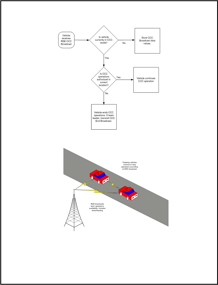 SAE J2735-Draft-Rev29 [issued: 12-11-08]
-
297 -
This is an SAE Motor Vehicle Council draft document of the DSRC committee, subject to change.
Figure 21: RSE CCC Broadcast Flow
Figure 22: RSE Team Operations Announcement
|
 SAE J2735-Draft-Rev29 [issued: 12-11-08]
-
298 -
This is an SAE Motor Vehicle Council draft document of the DSRC committee, subject to change.
Roadside Broadcast Message
Roadside broadcast message includes the following data elements:
DE_MessageType
o
Message Type
ShapePointSet
o
Area (zone or authorized lane)
DF_FullPositionVector
o
Heading
DE _Speed
o
Speed Limit: this value shall provide the system limits for target speed values utilized by the
vehicle teams.
DE _Max Team Vehicles
o
Max Vehicles Per Team
DE _VehicleType
o
Vehicle Class – Utilize J2735 Vehicle types
6. Leave Team Message Operations
Vehicles are allowed to leave from any position within the team.
Any vehicle will be allowed to leave the team at any time.
The Leave event should be an event-based trigger or active control of the vehicle. Active control
should be something similar to cruise control features already in place, such as a driver pressing on the
brake. A trigger may also be a team-specific limit, such as a destination reached, or the team dynamics
have changed.
The vehicle should define an allowable separation distance threshold. The separation threshold will
define a threshold that the vehicle will maintain during teaming operations. If the separation threshold
is exceeded, the vehicle may choose to leave the team or adjust its threshold to maintain teaming
operations.
Prior to Leaving a team, the vehicle shall increase its separation distance to the next vehicle to enable
safe human-controlled operations.
|
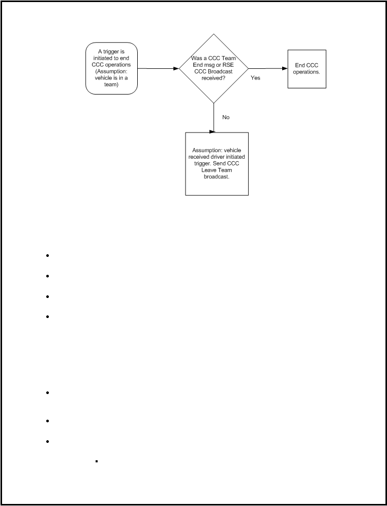 SAE J2735-Draft-Rev29 [issued: 12-11-08]
-
299 -
This is an SAE Motor Vehicle Council draft document of the DSRC committee, subject to change.
Figure 23: High-level CCC “Leave” Process Flow
Leave Message Broadcast
Leave Message broadcast includes the following data elements:
DE_MessageType
o
Message Type
DF_DDateTime
o
Timestamp
DE _Team Position Number
o
Position (Team Position)
Leave identifier
o
Switch Lanes
o
Turn Right/Left
o
Speed Change
6. Team Status Message Operations
Team members should broadcast current position information.
Vehicles will broadcast A “Status” message that provides location information to surrounding
members of the team. The frequency of this message will depend on factors such as vehicle speed and
following distance.
The teaming status message may be linked to map applications for other use-cases such as private
teams that specify a destination.
Status data elements
o
DE_MessageType
Message Type
|
 SAE J2735-Draft-Rev29 [issued: 12-11-08]
-
300 -
This is an SAE Motor Vehicle Council draft document of the DSRC committee, subject to change.
o
DF_DDateTime
Timestamp
o
DF_FullPositionVector
Position
Heading
o
DE _Team Identifier
Team ID
o
DE _Team Position Number
Position ID
o
DE _Speed
Target Speed
o
DE _Speed
Speed
o
DE _Num Team Vehicles
Number of Vehicles
7. Conclusion
From the requirements listed above, the following initial data sets are envisioned. This list is not meant to
be exhaustive, but gives us the initial operations for a functioning team. Further complex datasets are
envisioned.
V2V messaging
o
Team Status Message
o
Begin
o
End
o
Join
o
Leave
RSE Service Announcement
o
Zone Identification
o
Signal Phase and Timing (SPAT) Information
o
Road/Weather/Traffic Conditions
|
 SAE J2735-Draft-Rev29 [issued: 12-11-08]
-
301 -
This is an SAE Motor Vehicle Council draft document of the DSRC committee, subject to change.
8. Developer Notes
Vehicle Class Compatibility
Cooperative Cruise Control systems utilizing this message set aim to increase mobility, safety, and fuel –
efficiency through enabling low-latency communications between vehicles. Such communications provide
information which allow shorter distances or separation between two vehicles traveling in the same
direction, in the same lane, and at the same speed. A team shall be made up of similar or compatible
vehicle types in order to achieve the same operational characteristics and safety between team vehicles.
Different vehicle platforms have significantly different operational characteristics and therefore make the
benefits to safety and mobility unachievable. For instance, a passenger vehicle and a freight truck have
different acceleration, braking, turning, and reaction characteristics. It would be extremely unlikely if not
feasible at all to implement a system where the two could co-exist in the system environment envisioned
for Cooperative Cruise Control.
Leader to Team Communications
The purpose of the Cooperative Cruise Control message set is to provide a mechanism to improve the
mobility throughput, fuel efficiency and vehicular safety of the roadway through the use of a team or
collective of vehicles. Industry expert experience involved with committee brought to bear during the
development of this message set deem communications between the team leader and team members must
be direct. Direct communications is defined as receiving the message packets directly from the sender of
the packets themselves and not being relayed those packets through an intermediary or other mechanism.
The side effect of in-direct communications proves to undermine the intent of the message set. Even
through the use of low-latent communications, a lag or latency exists between the time a team leader sends
a message and when a team member receives the message directly. Should an intermediary have to receive
the message and relay to following team members the benefit of the information contained in the message
is reduced or lost. In some cases, the effect may be increased. Thus, instead of improving vehicular
reaction time in response to external variables, vehicle reaction times may decrease. The result may
increase the traffic caterpillar or slinky effect. This is also known as adversely affecting the string stability
of the vehicle team.
Reducing the caterpillar effect is the overarching goal of the message set. This is achieved or accomplished
by maintaining team size limits, vehicle class compatibility within teams, and direct communications with
the team leader. These factors may change given the type of low latent communications utilized.
Alterations are left to the implementation of the system.
Broadcast Strategy
The cooperative Cruise Control message set as defined in this document follows a broadcast or non-
acknowledgment response strategy. A broadcast strategy is one in which the communications
infrastructure necessitates a handshaking mechanism which includes dedicated or verified connection.
There is no intent to provide a sense of ad-hoc mobile network functionality through the use of this
message set. That said, vehicle networks based on ad-hoc networking or some other strategy may still use
this message set without needing to modify the message set structure.
Teaming Speed Limit
The teaming concept provides a strategy for vehicles traveling with similar goals, such as speed, heading,
and roadway lane. The strategy is intended to improve mobility, roadway throughput, reduce roadway
|
 SAE J2735-Draft-Rev29 [issued: 12-11-08]
-
302 -
This is an SAE Motor Vehicle Council draft document of the DSRC committee, subject to change.
caterpillar effect, and improve fuel efficiency to name a few. However, these goals must not be achieved
by exceeding the roadway limitations as governed by Federal, State and Local authorities and agencies.
Thus, the broadcasting of the speed limit value for the teaming zone provides the speed limitation required
for safe and successful teaming operations in the particular zone of interest. In absence of a speed limit, a
vehicle shall make the assumption that teaming operations are unavailable for the current zone. This
possibility may occur in areas where RSE coverage is not as saturated. Once a vehicle enters an RSE
coverage zone, authorization for teaming operations may be received.
FHWA Vehicle Classes
FHWA Vehicle Class has been previously defined for the SAE J2735. A detailed discussion of the FHWA
vehicle Class definitions may be found at the FHWA Office of Highway Policy Information. An excerpt of
this information follows.
FHWA Vehicle Classes with Definitions
Motorcycles -- All two or three-wheeled motorized vehicles. Typical vehicles in this category
have saddle type seats and are steered by handlebars rather than steering wheels. This category
includes motorcycles, motor scooters, mopeds, motor-powered bicycles, and three-wheel
motorcycles.
Passenger Cars -- All sedans, coupes, and station wagons manufactured primarily for the
purpose of carrying passengers and including those passenger cars pulling recreational or other
light trailers.
Other Two-Axle, Four-Tire Single Unit Vehicles -- All two-axle, four-tire, vehicles, other than
passenger cars. Included in this classification are pickups, panels, vans, and other vehicles such
as campers, motor homes, ambulances, hearses, carryalls, and minibuses. Other two-axle, four-
tire single-unit vehicles pulling recreational or other light trailers are included in this classification.
Because automatic vehicle classifiers have difficulty distinguishing class 3 from class 2, these two
classes may be combined into class 2.
Buses -- All vehicles manufactured as traditional passenger-carrying buses with two axles and
six tires or three or more axles. This category includes only traditional buses (including school
buses) functioning as passenger-carrying vehicles. Modified buses should be considered to be a
truck and should be appropriately classified.
NOTE: In reporting information on trucks the following criteria should be used:
1.
Truck tractor units traveling without a trailer will be considered single-unit trucks.
2.
A truck tractor unit pulling other such units in a "saddle mount" configuration will be
considered one single-unit truck and will be defined only by the axles on the pulling unit.
3.
Vehicles are defined by the number of axles in contact with the road. Therefore, "floating"
axles are counted only when in the down position.
4.
The term "trailer" includes both semi- and full trailers.
Two-Axle, Six-Tire, Single-Unit Trucks -- All vehicles on a single frame including trucks,
camping and recreational vehicles, motor homes, etc., with two axles and dual rear wheels.
Three-Axle Single-Unit Trucks -- All vehicles on a single frame including trucks, camping and
recreational vehicles, motor homes, etc., with three axles.
Four or More Axle Single-Unit Trucks -- All trucks on a single frame with four or more axles.
|
 SAE J2735-Draft-Rev29 [issued: 12-11-08]
-
303 -
This is an SAE Motor Vehicle Council draft document of the DSRC committee, subject to change.
Four or Fewer Axle Single-Trailer Trucks -- All vehicles with four or fewer axles consisting of
two units, one of which is a tractor or straight truck power unit.
Five-Axle Single-Trailer Trucks -- All five-axle vehicles consisting of two units, one of which is a
tractor or straight truck power unit.
Six or More Axle Single-Trailer Trucks -- All vehicles with six or more axles consisting of two
units, one of which is a tractor or straight truck power unit.
Five or fewer Axle Multi-Trailer Trucks -- All vehicles with five or fewer axles consisting of three
or more units, one of which is a tractor or straight truck power unit.
Six-Axle Multi-Trailer Trucks -- All six-axle vehicles consisting of three or more units, one of
which is a tractor or straight truck power unit.
Seven or More Axle Multi-Trailer Trucks -- All vehicles with seven or more axles consisting of
three or more units, one of which is a tractor or straight truck power unit.
9. Message Set Human Interaction
The message set concept follows a fundamental operational paradigm which assumes automatic operation
of the system. This means that once the system is turned on via human interaction the system operates
based on system parameters and implementation criteria. However, pertinent messages are received from
the vehicle team or the roadside infrastructure which detail operational status or operational changes which
may be of interest to the driver. This information may be presented to the driver via the display in a similar
manner as other defined traveler information messages. The current intent is not to provide system
interaction for the driver but only provide system and team interaction monitoring.
The following text is informational only. It is used in the automatic creation and building of the document.
It will not be a part of the standard when balloted.
Text created by First_Word Version: 0.8.270 On node C:136-5448-3969
Run finished at: 12/11/2008 3:49:25 PM and used about 3348 seconds of core automation.
Use:
Auto-updated draft document.
Create_time:
03:49:27 PM Thursday, December 11, 2008
Extracted from:
Dsrc_rev029.ITS
[Mod: 12/11/2008 2:49:16 PM]
Styles from:
DSRC_Template.doc
[Mod: 11/10/2008 5:53:37 PM]
Included Files:
Section_Two.doc
[Mod: 11/10/2008 5:54:56 PM]
Section_Four.doc
[Mod: 11/10/2008 6:00:19 PM]
Section_End.doc
[Mod: 12/11/2008 2:43:49 PM]
Build:
First_Word, Ver: 0.8.270 On node C:136-5448-3969
Written to:
DSRC_J2735_RevXX.doc
[private file name]
Current at:
An internally developed product of SCSC.
Part of the www.ITSware.net tool system.
A copyright assignment to the SDO replaces these
lines when balloted.
|