 |
 |
|
SAE J2735-Draft-Rev29 [issued: 12-11-08]
-
288 -
This is an SAE Motor Vehicle Council draft document of the DSRC committee, subject to change.
The lane set lists all the lanes (by their assigned number defined in the GID-MAP) that share this common
state and period. The currState element indicates the specific type of light (i.e. through arrow green,
yellow flashing etc.) present. The timeToChange indicates the minimum value of time for which this state
will persist in a count down timer. An optional confidence value may follow this and allows asserting
complex concepts like min or max times or times which are likely to change in adaptive intersections. A
second (optional) state called the “yellow state” allows sending phase time data about the NEXT phase of
the state and its duration. Its use will vary by local policies, but it is useful in relating yellow times as well
as pedestrian walkway clearance times. Various other optional data elements can also be sent including
the number of vehicles that have been detected or counted in the lane.
3.
The overall framework of the MAP
The MAP message is used to convey a number of different types of (static) maps in support of DSRC
messages. The intersection is but one kind of such data. Some of these remain to be defined in future
editions of the standard. However, the “intersections” or GID portion of the map is defined and is used
along with the SPAT message to relate information about intersections.
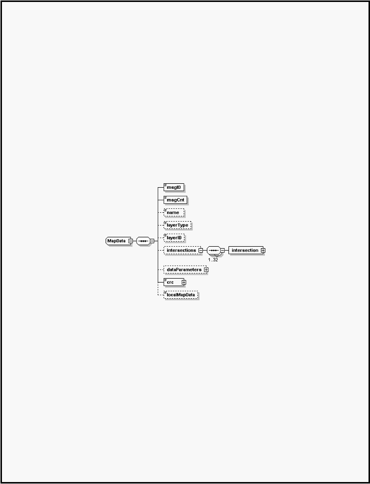
The intersection data frame, shown below, is used to relate all the needed physical geometry of an
intersection, assign the intersection a unique ID, and to assign numbers to specific lanes (the set of lanes
being a sub-set of an approach). Up to 32 intersections can be contained in a single map message.
Intersections are defined as collections of approaches, which are in turn defined as a collection of related
lanes. Each intersection has a regionally unique ID associated with this. It may optionally have a name
string as well. A reference point is used to define a precise position from which local offset values are used
to describe the geometry of the lanes. Other, optionally present reference points can be further defined in
the structures when needed to simplify extremely complex intersections. Intersections, like traffic lanes,
often follow repeating patterns, so a data compression scheme that allows “computed intersections” to
replicate simple intersections is provided (data elements refInterNum and orientation support this)